Table of Contents
Advertisement
Quick Links
TH1400NP
Installation Guide
Non-Programmable
Low Voltage Thermostat (24 Vac)
AUXILIARY OUTPUT
The thermostat provides an auxiliary heating output that
can act as a second stage of heating when controlling
ambient temperature.
If the room temperature is too far from the setpoint or the
main stage of heating has difficulties raising the
temperature, the auxiliary output activates the secondary
heating source to reach the set temperature.
Both outputs can control different types of heating load and
can be configured in the user settings.
CONNECTION OF THE FLOOR SENSOR
(OPTIONAL)
Only for control applications in floor (F) mode or with floor limit.
1
Unlock and lift the
thermostat cover.
4
Use the provided screws and
wall anchors to fix the
thermostat base on the wall.
WIRING LAYOUT
Electric baseboard
Electric floor heating with electric
baseboard on the 2nd heating stage
When installing your floor heating system: add a
second sensor in the floor and store the tip in the
thermostat housing. This additional sensor can be
plugged in and used as a replacement without
haltering your floor heating system.
Sensor
INSTALL YOUR THERMOSTAT
If necessary, mark and drill the
2
appropriate fastening holes, using the
installation template. If needed, use
the wall anchors included.
5
Replace back and lock the
thermostat cover.
Hot water valve
C
Electric baseboard
R
W1
W2
S1
S 2
Electric floor heating
Floor sensor
Electric baseboard
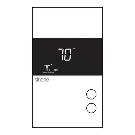
Increasing or lowering the temperature
To adjust the temperature, press
will blink to confirm the new setpoint.
3
Depending on the heating system,
insert each wire into its terminal
and screw firmly. (See connection
layouts outlined in the following
pages.)
6
Power up the thermostat.
Set
Set
120 V
24 V
240 V
24 Vac
347 V
Valve
normally open
For use in floor or ambient
Floor sensor
mode with floor limit.
Not required for ambient
mode alone.
or
. The requested temperature
Set
Set
Advertisement
Table of Contents

Subscribe to Our Youtube Channel
Related Manuals for Sinope TH1400NP


Summary of Contents for Sinope TH1400NP
- Page 1 If needed, use and screw firmly. (See connection the wall anchors included. layouts outlined in the following pages.) TH1400NP Installation Guide Non-Programmable Low Voltage Thermostat (24 Vac) Use the provided screws and Power up the thermostat.
- Page 2 • Hydronic heating system • Furnace (without fan control) SINOPE TECHNOLOGIES INC. warrants the components of their products against defects in material and workmanship for a 3-year period from the date of purchase, under normal use and service, when proof of purchase of such is provided to the manufacturer.
Need help?
Do you have a question about the TH1400NP and is the answer not in the manual?
Questions and answers