Table of Contents
Advertisement
Quick Links
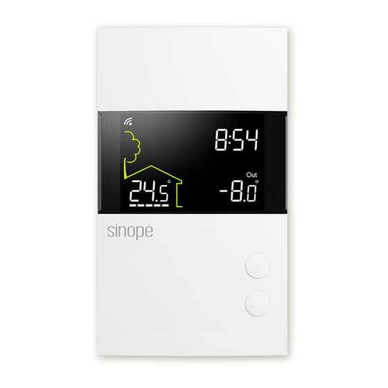
TH1400WF
Installation Guide
Smart Low voltage Thermostat (24 Vac)
AUXILIARY OUTPUT
The thermostat provides an auxiliary heating output that
can act as a second stage of heating when controlling
ambient temperature.
If the room temperature is too far from the setpoint or the
main stage of heating has difficulties raising the
temperature, the auxiliary output activates the secondary
heating source to reach the set temperature.
Both outputs can control different types of heating load and
can be configured in the user settings.
CONNECTION OF THE FLOOR SENSOR
(OPTIONAL)
Only for control applications in floor (F) mode or with floor limit.
TB024B
1
Unlock and lift the
thermostat cover.
4
Use the provided screws and
wall anchors to fix the
thermostat base on the wall.
WIRING LAYOUT
Electric baseboard
Electric floor heating with electric
baseboard on the 2nd heating stage
ADD YOUR THERMOSTAT TO NEVIWEB
1
If you do not have an account yet,
download the Neviweb app for iOS or
Android to open an account and add
your device.
Sensor
3
Follow the steps of the
Installation Wizard
INSTALL YOUR THERMOSTAT
If necessary, mark and drill the
2
appropriate fastening holes, using the
installation template. If needed, use
the wall anchors included.
5
Replace back and lock the
thermostat cover.
Hot water valve
C
Electric baseboard
R
W1
W2
S1
S 2
Electric floor heating
Floor sensor
Electric baseboard
2
Tap the
1
2
3
3
Depending on the heating system,
insert each wire into its terminal
and screw firmly. (See connection
layouts outlined in the following
pages.)
6
Power up the thermostat.
120 V
24 V
240 V
24 Vac
347 V
normally open
For use in floor or ambient
Floor sensor
mode with floor limit.
Not required for ambient
mode alone.
then select "Add Device"
Valve
Advertisement
Table of Contents

Related Manuals for Sinope TH1400WF


Summary of Contents for Sinope TH1400WF
- Page 1 If needed, use and screw firmly. (See connection the wall anchors included. layouts outlined in the following pages.) TH1400WF Installation Guide Smart Low voltage Thermostat (24 Vac) Use the provided screws and Power up the thermostat. Replace back and lock the wall anchors to fix the thermostat cover.
- Page 2 (SSR) of the device. • Electric floor heating (activated by a relay) SINOPE TECHNOLOGIES INC. warrants the components of their products against • Hydronic floor heating This equipment has been tested and found to comply with the limits for a defects in material and workmanship for a 3-year period from the date of purchase, •...
Need help?
Do you have a question about the TH1400WF and is the answer not in the manual?
Questions and answers