Table of Contents
Advertisement
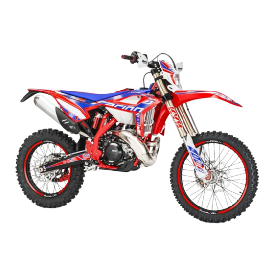
XTRAINER 250 2T EUROPA - XTRAINER 300 2T EUROPA
XTRAINER 250 2T - XTRAINER 300 2T
Thanks for you preference, and have a good time! This hand-
book contains the information you need to properly operate and
maintain your motorcycle.
The data, specifications and images shown in this manual does not constitute
an engagement on the part of BETAMOTOR S.p.A. BETAMOTOR reserves
the right to make any changes and improvements to its models at any mo-
ment and without notice.
Code 036440210 000
EN
1
Advertisement
Chapters
Table of Contents
Troubleshooting

Related Manuals for Beta Motorcycles XTRAINER 250 2T EUROPA 2022


Summary of Contents for Beta Motorcycles XTRAINER 250 2T EUROPA 2022
- Page 1 XTRAINER 250 2T EUROPA - XTRAINER 300 2T EUROPA XTRAINER 250 2T - XTRAINER 300 2T Thanks for you preference, and have a good time! This hand- book contains the information you need to properly operate and maintain your motorcycle. The data, specifications and images shown in this manual does not constitute an engagement on the part of BETAMOTOR S.p.A.
- Page 2 IMPORTANT We recommend you to check all the tightenings after the first one or two hours’ ride over rough ground. Special attention should be paid to the following parts: • rear sprocket • ensure that the footrests are properly fixed •...
-
Page 3: Table Of Contents
CONTENTS Operating instructions ................5 Symbols ....................5 Riding safety ..................6 CHAPTER 1 GENERAL INFORMATION ..........7 Vehicle identification data ............... 8 Tools kit ....................8 Familiarizing with the vehicle..............9 Specifications ..................10 Electrical system ................... 14 Recommended lubricants and liquid ............16 CHAPTER 2 OPERATION .............. - Page 4 Carburettor ..................54 Front brake..................56 Rear brake ..................59 Clutch control ..................62 Check and adjusting of steering play ............64 Front wheel ..................65 Fork ....................66 Rear suspension leverage ..............66 Tyres....................67 Chain ....................67 Headlight .................... 69 Replacing the headlight bulbs ..............
-
Page 5: Operating Instructions
OPERATING INSTRUCTIONS • The vehicle must be accompanied by: number-plate, registration document, tax disc and insurance. • Any modifications of the engine or other parts are punishable by severe sanctions including the confiscation of the vehicle. • To protect your safety and that of others, always drive carefully and with your helmet on and always keep low beams on. -
Page 6: Riding Safety
RIDING SAFETY • Observe the Highway Code. • Always wear approved personal protective equipment. • Always ride with the low beam on. • Always keep the crash helmet visor clean. • Avoid wearing garments with hanging ends. • Do not keep sharp or brittle objects in your pockets while riding. •... -
Page 7: Chapter 1 General Information
CHAPTER 1 GENERAL INFORMATION CONTENTS Vehicle identification data ............... 8 Frame identification ................8 Engine identification ................8 Tools kit ....................8 Familiarizing with the vehicle..............9 Main parts: ..................9 Specifications ..................10 Weight ................... 10 Dimensions ..................10 Tyres .................... -
Page 8: Vehicle Identification Data
VEHICLE IDENTIFICATION DATA FRAME IDENTIFICATION Frame identification data A are stamped on the right side of the steering head tube. ENGINE IDENTIFICATION Engine identification data B are stamped in the area shown in the figure. TOOLS KIT The following items are supplied as stan- dard: operation, maintenance manual, tool kit and the cable adapter to connect the CAN socket to a scantool. -
Page 9: Familiarizing With The Vehicle
FAMILIARIZING WITH THE VEHICLE MAIN PARTS: 1 - Fuel tank 10 - Lower bumper 17 - Rear side panel 2 - Tank cap (Bumper kit) 18 - Rear mudguard 3 - Silencer 11 - Saddle 4 - Rear shock absorber 12 - Engine 5 - Headlight 13 - Front mudguard... -
Page 10: Specifications
SPECIFICATIONS WEIGHT Weight in running order with full fuel and optional .............. 115 kg (front 55 Kg; rear 60 Kg) DIMENSIONS maximum length (with plate holder) ..........2270 mm maximum width ................802 mm overall height ................1245 mm wheelbase................. 1467 mm saddle height ................ - Page 11 FRONT SUSPENSION Hydraulic fork USD (shafts Ø43 mm) Spring ....................K 8 Oil type ....see table “Recommended lubricants and liquids”, page 16 Oil quantity ...................500 ml Spring preload register ............completely open Rebound clicks (from completely closed) ..........12 Wheel travel................
- Page 12 ENGINE Version XTRAINER 250 2T Europa XTRAINER 300 2T Europa XTRAINER 250 2T XTRAINER 300 2T Type Single-cylinder, 2-stroke, liquid cooled and electric start Bore x stroke [mm] 66,4 x 72 72 x 72 Displacement [cm³] 293,1 Compression ratio 13,5:1 11,4:1 [g/km] * # Fuel consumption [l/100km] * #...
- Page 13 Gearchange Version XTRAINER 250 XTRAINER XTRAINER 300 XTRAINER 2T Europa 250 2T 2T Europa 300 2T Primary drive 27/72 27/72 27/72 27/72 Gear ratio 1 gear 12/31 12/31 12/31 12/31 Gear ratio 2 gear 15/28 15/28 15/28 15/28 Gear ratio 3 gear 19/28 19/28...
-
Page 14: Electrical System
ELECTRICAL SYSTEM ELECTRICAL DIAGRAM Key to colours Bi = White Ve = Green Ma = Brown Vi = Purple Bl = Blue Ne = Black Gi = Yellow Rs = Red Ar = Orange Az = Sky-blue Ro = Pink Gr = Grey... - Page 15 LEGEND ELECTRICAL DIAGRAM RIGHT-HAND FRONT TURN INDICATOR 12V 6W FRONT BRAKE LIGHT BUTTON START BUTTON ENGINE STOP BUTTON WHEEL REVOLUTION SENSOR TURN INDICATORS WARNING LIGHT BUTTON 1 OIL RESERVE WARNING LIGHT DASHBOARD HEADLIGHT TELL TALE LAMP BUTTON 2 DIAGNOSIS WARNING LIGHT HORN BUTTON FLASH-TO-PASS BUTTON HEADLIGHT SELECTOR...
-
Page 16: Recommended Lubricants And Liquid
RECOMMENDED LUBRICANTS AND LIQUID To maximize the vehicle’s performance and ensure many years of trouble-free opera- tion, we recommend using the following products: PRODUCT TYPE SPECIFICATIONS OIL MIXER TANK LIQUI MOLY 2-STROKE MOTOR OIL, SELF-MIXING GEAR AND CLUTCH OIL LIQUI MOLY RACING 10W40 BRAKE OIL LIQUI MOLY BRAKE FLUID DOT 5.1 CLUTCH ACTUATOR OIL... -
Page 17: Chapter 2 Operation
CHAPTER 2 OPERATION CONTENTS Main parts ..................18 Fuel tank cap .................. 18 Fuel cock ..................18 Starter .................... 19 Mixer oil tank cap ................19 Leva della frizione ................19 LH switch ..................20 RH switch ..................20 Front brake lever and gas control ............20 Gear change lever................ -
Page 18: Main Parts
MAIN PARTS FUEL TANK CAP To open the fuel tank cap, turn it anticlock- wise. To close the fuel tank cap, set it on the tank and screw it clockwise. FUEL COCK Fuel cock has three positions: OFF: fuel supply closed. Fuel cannot pass from the tank to the carburettor. -
Page 19: Starter
STARTER The starter lever is located on the carbu- rettor. To operate the choke pull it upward. MIXER OIL TANK CAP The mixer oil tank cap is located under the saddle To gain access remove the saddle (page 80). To open the fuel tank cap turn it anticlock- wise. -
Page 20: Lh Switch
LH SWITCH The dip and service switch is located on the left side of the handlebar and is com- posed as follows: 1 - Horn button; 2 - Dip switch: parking lights and high beam; parking lights and low beam; 3 - Flash-to-pass button;... -
Page 21: Gear Change Lever
GEAR CHANGE LEVER Gear change lever is fitted to the left side of the engine. The positions corresponding to the different gears are shown in the figure. BRAKE PEDAL Brake pedal is located in front of the right- hand footrest. The rear brake is operated by pressing down the pedal. -
Page 22: Keys
If the vehicle is used off-road, the closed stand can be further fastened by means of rubber band. KEYS The vehicle is supplied with two keys (one key and its spare). STEERING LOCK To activate the steering lock: - turn the handlebar counter-clockwise; - push the key and turn counter-clockwise;... -
Page 23: Digital Rpm Indicator Operating Instructions
DIGITAL RPM INDICATOR OPERATING INSTRUCTIONS Index General information Operating condition General characteristics Dashboard start-up process 3.1.1 Wake up events LCD Display 3.2.1 LCD general characteristics 3.2.2 Speed 3.2.3 Odometer 3.2.4 Trip A 3.2.5 Trip B 3.2.6 Clock 3.2.7 Ride Time 3.2.8 Unit option display 3.2.9... - Page 24 3 GENERAL CHARACTERISTICS 3.1 DASHBOARD START-UP PROCESS The dashboard do some start-up process when is turned ON. There are three differ- ent wakes up events for starting the dashboard. This start-up process consists in turning ON the LCD backlight and the LCD will show all the segments during 2 seconds.
- Page 25 3.2.1 LCD GENERAL CHARACTERISTICS Each information/data is refreshed independently at different rates, depending on information type and variability of this information. 3.2.2 SPEED Dashboard computes and displays the motorbike speed on LCD display. Speed information can be obtained from: Dedicated digital input for measuring speed sensor frequency. 3.2.2.1 Speed digital input configuration Configuration parameters for speed input and speed visualization.
- Page 26 3.2.3 ODOMETER Dashboard provides an odometer and is displayed on LCD display. This option can be displayed scrolling by “MODE” button. 6 digits and “ODO” icon lighted. Leading zeros not suppressed. Display range from 000000 to 999999 km or miles. If odometer is greater than 999999 km, odometer will be fixed as 999999km.
- Page 27 3.2.5 TRIP B This option can be displayed scrolling by “MODE” dashboard button. 4 digits (3digits + decimal point + 1 digit), “TRIP” icon lighted and “B” on the left. Leading zeros suppressed. Display range from 0.0 to 999.9 km or miles. Trip B counter counts from 0 up to 999.9 and then rolls over to 0 and continue counting.
- Page 28 3.2.7 RIDE TIME Dashboard provides a Ride Time and is displayed on LCD display. Time is obtained from internal crystal quartz and is kept with a push buttons. When the motorbike is turned on the ride time starts again. 3.2.8 UNIT OPTION DISPLAY Dashboard provides the possibility to change the units and be displayed.
- Page 29 3.2.10 MOTORBIKE BATTERY LEVEL Dashboard displays level of voltage of battery power supply: Relationship between bars and level of voltage: Bars Voltage [V] Bars Voltage [V] 0 1 4 5 1 2 11.5 5 6 13.5 2 ...
- Page 30 Mode Speed Function Button Time Activity (sec) CLOCK “On Entering Stop MODE <2 Increase in the Hour digits MODE Clock Mode“ MODE >2 Speedy increase in the Hour digits <2 Increase in the minutes digits >2 Speedy increase in the minutes digits MODE&SET >2 Exit clock set mode and save the value...
- Page 31 3.3 TELLTALES LED number indicator: LED 1 LED 2 LED 3 LED 4 Telltales/Indicator lights specifications: Number of telltales: 4 LED number Function Symbol LED 1 Blinkers LED 2 High beam LED 3 Oil Reserve MIL telltale (Engine management LED 4 system fault)
- Page 32 Power +12V are provided to the dashboard only when the bike is turned on (regulator line). Blinkers LED The system activates the indicator in synchrony with the activation of the direction indicators High beam LED The system activates the indicator in synchrony with the activation of the high beam. Oil reserve LED MIL LED Indicates a fault in the engine management system.
-
Page 33: Checks Before And After Use
CHECKS BEFORE AND AFTER USE For safe driving and long vehicle life you should: 1 Check the integrity of the oil pipe connecting the intake manifold to the electronic dosing. 2 Check all fluid levels. 3 Check the correct operation of the brakes and brake pad wear (page 56). 4 Check pressure, general condition and thickness of tread (page 67). -
Page 34: Refuelling
REFUELLING Use unleaded petrol. Fuel tank capacity is shown on page 10. To refuel open the tank cap (page 18). After refuelling, screw the cap back and tighten securely. WARNING The refuelling should be performed with the engine off. WARNING Fire hazard. -
Page 35: Oil Mixer Refuelling
OIL MIXER REFUELLING To refuel open the tank cap (page 19). Fuel tank capacity is shown on page 10. After refuelling, screw the cap back and tighten securely. Use the oil indicated on page 16 in the “Recommended lubricants and liquids” table. -
Page 37: Chapter 3 Adjustments
CHAPTER 3 ADJUSTMENTS CONTENTS Key to symbols..................38 Brakes ....................38 Front brake ..................38 Rear brake ..................38 Clutch ....................38 Adjustment of gas clearance ..............39 Adjusting the idle speed ................ 39 Carburetor settings according to the working conditions ....... 40 Exhaust valve control adjustment ............ -
Page 38: Key To Symbols
KEY TO SYMBOLS Tightening torque Threadlocker Medium BRAKES FRONT BRAKE The front brake is disk type with hydraulic control. The home position of brake lever 2 can be adjusted by means of screw 1. REAR BRAKE The home position of brake pedal 3 can be altered by turning adjusting screw 5 af- ter loosening the counternut located under dust cap 4. -
Page 39: Adjustment Of Gas Clearance
ADJUSTMENT OF GAS CLEARANCE The throttle control cable should always have a 3-5 mm play. In addition, the idle speed should not change when the han- dlebars are fully rotated to the left or right. Push back protective cap 1. Loosen coun- ternut 2 and turn adjusting screw 3. -
Page 40: Carburetor Settings According To The Working Conditions
To properly adjust the idle speed, follow these steps: • Tighten the air adjustment screw no. 2 fully and then loosen it up to the value described in the carburetor setting table (page 12) • Warm the engine for approx. 5 minutes, until the operational temperature is attained. • Slowly turn the air adjustment screw 2 clockwise, until idling starts diminishing. - Page 41 XTRAINER 250 2T Altitude Carburetor Ambient temperature (SLM) setting -20°C÷ -6°C÷ 6°C ÷ 16°C ÷ 25°C ÷ 37°C ÷ ÷-7°C 5°C 15°C 24°C 36°C 49°C -2°F ÷ 19°F ÷ 42°F ÷ 61°F ÷ 79°F ÷ 99°F ÷ 20°F 41°F 60°F 78°F 98°F 120°F...
- Page 42 XTRAINER 300 2T Altitude Carburetor Ambient temperature (SLM) setting -20°C -6°C÷ 6°C ÷ 16°C ÷ 25°C ÷ 37°C ÷ ÷-7°C 5°C 15°C 24°C 36°C 49°C -2°F ÷ 19°F ÷ 42°F ÷ 61°F ÷ 79°F ÷ 99°F ÷ 20°F 41°F 60°F 78°F 98°F 120°F...
-
Page 43: Exhaust Valve Control Adjustment
EXHAUST VALVE CONTROL ADJUSTMENT ATTENTION! The vehicle is provided with an exhaust valve whose fine tuning is performed during the final try-out of the engine. The position of adjustment valve 1 must not be modified for any reason. For any adjusting, please contact Betamo- tor’s Authorized Service Network. -
Page 44: Adjusting Fork
Apply the handlebar. Apply the top u-bolt. Refit the screws 6. Tighten to the torque indicated. 25Nm ADJUSTMENT OF THE HANDLEBAR POSITION The handlebar can be adjusted by rotating it back and forth. To adjust the handlebar loosen screws 1. Position the handlebar according to re- quirements. -
Page 45: Shock Absorber
SHOCK ABSORBER ADJUSTING THE REBOUND DAMPER Turn screw A to adjust the hydraulic re- bound damper. For adjustment refer to the table on the side. Increase Decrease For standard setting, refer to page 11. braking effect braking effect ADJUSTING THE HYDRAULIC COMPRESSION DAMPER Turn knob A to adjust the hydraulic com- pression damper. -
Page 46: Adjusting The Spring Preload
ADJUSTING THE SPRING PRELOAD To adjust the spring preload, use the pro- cedure described below: Loosen the locking dowel A. Turn the ring nut B until you reach the desired preload. Lock the locking dowel A. For standard setting, refer to page 11. Note: for movement of the rings use a specific sector key with square pin. -
Page 47: Chapter 4 Checks And Maintenance
CHAPTER 4 CHECKS AND MAINTENANCE CONTENTS Key to symbols...................48 Engine oil ....................48 Check the level ..................48 Replacement ..................48 Liquid coolant ....................49 Check the level ..................49 Replacement ..................50 Air filter ....................52 Removing and installing air filter .............52 Air filter cleaning - XTRAINER 250/300 2T ..........53 Spark plug ....................53 Carburettor ....................54 Draining the carburettor float chamber .............54... -
Page 48: Key To Symbols
KEY TO SYMBOLS Tightening torque Threadlocker Medium ENGINE OIL CHECK THE LEVEL Hold the vehicle upright. Position the drive on a flat base ensuring stability. Remove the inspection cap 1. The oil level must arrive to the lower edge of check hole. Otherwise restore the oil level through plug 2. -
Page 49: Liquid Coolant
- Unscrew filler plug 1 and drain plug 2. - Drain all the oil from the crankcase. - Place the cap 2 and tighten to specified torque. Pour in the quantity of liquid indicated on page 10. Use the oil indicated on page 16 in 15Nm the “Recommended lubricants and liquids”... - Page 50 WARNING: Wear appropriate protective cloth- ing and protection gloves. Keep coolant out of reach of chil- dren. Avoid any direct contact of the cool- ant with skin, eyes or clothing. If this happens: - with the eyes, rinse immediately with plenty of water and seek medical advice;...
- Page 51 - Unscrew drain screw 3. - Proceed to filling. - Reapply the loading cap and the bleed- ing screw. The amounts of liquid are shown on page Use the liquid indicated on page 16 in the “Recommended lubricants and liquids” table.
-
Page 52: Air Filter
AIR FILTER Check after every ride. REMOVING AND INSTALLING AIR FILTER To access the filter is necessary: •Remove the saddle (page 80). •Pull the cover air filter (page 81). •Release filter fastener 1. •Pull out air filter 2. WARNING: After every intervention, check that nothing has been left inside the filter box. -
Page 53: Spark Plug
AIR FILTER CLEANING - XTRAINER 250/300 2T EUROPA Blow the filter with compressed air. AIR FILTER CLEANING - XTRAINER 250/300 2T • Thoroughly wash the filter with water and soap. • Dry the filter. • Wet the filter with filter oil and then remove the excess oil to prevent it from drip- ping. -
Page 54: Carburettor
CARBURETTOR DRAINING THE CARBURETTOR FLOAT CHAMBER If the carburettor tank needs to be emptied, proceed as described. Remove the chain protection 1, close the tank tap and put a cloth under the carbu- rettor, so that you can collect the running out fuel. - Page 55 WARNING: Risk of poisoning! Fuel is poisonous liquid and a health hazard. Wear appropriate protective cloth- ing and protection gloves. Fuel must not come into contact with the skin, eyes, and clothing. Do not breathe in the fuel vapours. If contact occurs with the eyes, rinse immediately with plenty of water and seek medical advice.
-
Page 56: Front Brake
FRONT BRAKE CHECK THE LEVEL OF THE FRONT BRAKE FLUID Check the level of the brake fluid through sight A. The level of the fluid should never fall below the mark in the sight. RESTORING THE LEVEL OF THE FRONT BRAKE FLUID To restore the level of the brake fluid, loosen the two screws 1, lift cap 2 and add brake fluid until its level is 5 mm below the upper... - Page 57 BLEEDING THE FRONT BRAKE To bleed air from the front brake circuit, proceed as follows: •Remove the rubber cap 1 from the valve 2. •Open the sump cap. •Place one end of a small transparent tube into the valve 2, and the other end inside a container.
- Page 58 FRONT BRAKE LINING CONTROL In order to verify the wear condition of front brake is enough to view the caliper from the bottom, where is possible to glimpse the brake lining tails which will have to show a brake of 2 mm in thickness. If the stratum is lesser let’s start replacing them.
-
Page 59: Rear Brake
REAR BRAKE CHECK THE LEVEL OF THE REAR BRAKE FLUID Check the level of the brake fluid through sight A. The level of the fluid should never fall below the mark in the sight. RESTORING THE LEVEL OF THE REAR BRAKE FLUID To restore the oil level, top up by means of oil filler cap 1. - Page 60 BLEEDING THE REAR BRAKE To bleed air from the rear brake circuit, proceed as follows: •Remove the rubber cap 1 from the valve 2. •Open the sump cap. •Place one end of a small transparent tube into the valve 2, and the other end inside a container.
- Page 61 REAR BRAKE LINING CONTROL In order to verify the wear condition of rear brake is enough to view the caliper from above, where is possible to glimpse the brake lining tails which will have to show a brake of 2 mm in thickness. If the stratum is lesser let’s start replacing them.
-
Page 62: Clutch Control
CLUTCH CONTROL CHECK THE LEVEL To check the oil level in the clutch pump, first remove cover 2. Remove the two screws 1 and take off cover 1 together with the rubber bellows. With the clutch pump in a horizontal posi- tion, the level of the oil should be 5 mm below the upper rim. - Page 63 BLEEDING To bleed air from the clutch pump, proceed as follows: • Remove the rubber cap 1 from the valve 2. • Open the sump cap. • Place one end of a small transparent tube into the valve 2, and the other end inside a container.
-
Page 64: Check And Adjusting Of Steering Play
CHECK AND ADJUSTING OF STEERING PLAY Periodically check the play in the steering sleeve by moving the fork back and forth as shown in the figure. Whenever you feel play, adjust as described below: - Loosen the screws 1 - Loosen the screw 2 - Reduce the play by turning nut 3 Tighten the screws to the prescribed torque values. -
Page 65: Front Wheel
FRONT WHEEL TIGHTENING Following removal of the wheel: • Compress and release the fork 3-4 times. • Tighten the wheel bolt and the screws of the foot-leg. 20Nm 50Nm... -
Page 66: Fork
FORK 17Nm To maintenance refer at an authorized service center Betamotor. To check the tightening torques see as shown in the figure. WARNING: Tightening of the screws should be carried out by adjusting the torque wrench to the stability torque with repeated tightening until stability torque has been achieved. -
Page 67: Tyres
TYRES Only fit tyres approved by BETAMOTOR. Unsuitable tyres can adversely affect the road holding of the vehicle. • To protect your safety, immediately replace any damaged tyres. • Slick tyres adversely affect the road holding of the vehicle, especially on wet roads and in off-road riding. • Insufficient pressure results in abnormal wear and overheating of the tyres. • The front and rear tyres must have the same tread design. • Always measure the inflating pressures when the tyres are cold. • Keep the tyre pressures within the prescribed range. CHAIN Checking the drive chain periodically to ensure longer chain life. Always keep it lubricated and clean of deposited dirt. - Page 68 • Loosen counternuts A on either side of the fork. • Turn adjusting screws B on either side until the desired chain tension is obtained. • Tighten counternuts A on either side of the fork. • Tighten the pin 1 to the torque indicated. 130Nm CHECK FOR CHAIN WEAR 10 -15 Kg...
-
Page 69: Headlight
HEADLIGHT Keep the headlight glass clean at all times (see page 73). Periodically check the correct angle of the light beam. REPLACING THE HEADLIGHT BULBS Remove the fixing screws and move for- ward the lamp holder front cowl. Carefully remove the headlight bulb 1 together with lamp holder. -
Page 70: Battery
BATTERY Battery is located under the saddle and requires no maintenance. Keep the battery terminals clean. If neces- sary, protect them with a thin film of acid- free grease. BATTERY REMOVAL AND ASSEMBLY Remove the saddle (page 80). Release the rubber band. FIRST disconnect the negative connector (black) from negative (-) pole and THEN positive connector (black) from negative... - Page 71 INACTIVITY If the vehicle is not going to be used for a long time, remove the battery and charge it every 15 days using a suitable charger. Store the battery in a dry place at a tem- perature of 5 to 35°C and out of the reach of children.
-
Page 72: Fuses
FUSES To access the fuse, remove the saddle (page 80). In the case of blown fuse, the vehicle will not start/stop: Three spare fuses comes with the kit ac- companying the vehicle. A blown fuse should only be replaced with another of the same type. -
Page 73: Cleaning The Vehicle
CLEANING THE VEHICLE GENERAL PRECAUTIONS WARNING: Do not clean your vehicle with a high-pressure device with a strong jet of water. Excessive pressure can reach electrical components, con- nectors, flexible cables, bearings, etc and can damage or destroy them. WARNING: Wash motorbikes frequently with cold water that are used near the sea (salty air) and on roads subject to salt spreading in winter. -
Page 74: Prolonged Inactivity
PROLONGED INACTIVITY A few simple operations should be performed to keep the vehicle in good condition whenever it is to remain inactive for a long period (e.g. during the winter): • Thoroughly clean the vehicle. • Reduce the tyre pressures by approximately 30 percent, and if possible raise the tyres off the ground. -
Page 75: Scheduled Maintenance Vehicle
SCHEDULED MAINTENANCE VEHICLE Engine Gear and clutch oil Spark plug Head screws Engine clamping screws * Kick start and gearchange lever screws Spark plug cap Coated clutch disks Clutch springs length Clutch/bell hub Gearbox bearing (drive shaft side) Cylinder Piston and segments Connecting rod Drive shaft bearings Surface appearance of the gearbox... - Page 76 Brakes Liquid level, pads thickness Disc thickness Pipe tightness Idle travel levers and drives sliding Cycling Shock absorber and telescopic fork Rear suspension linkage Fork cover Bearings of stearing Bolts Wheels Wheel spokes and rim coaxiality Tyres (wear and pressure) Bearings clearance Check (Clean, adjust, lubricate, replace as necessary) Replace/renew...
-
Page 77: Tightening Torque Overview
TIGHTENING TORQUE OVERVIEW Here below is an overview of the tightening torque of all pieces subject to adjust- ment or maintenance: Forecarriage Tightening torque [Nm] Threadlock Wheel pin Fork foots - wheel pin Cavallotto parastelo sinistro Steering head base - fork legs Steering head - fork legs Stem pin on steering head Lower handlebar u-bolt - steering head... -
Page 79: Chapter 5 Replacements
CHAPTER 5 REPLACEMENTS CONTENTS Removal and refitting of the saddle............80 Removing and installing air filter cover panel ........... 81... -
Page 80: Removal And Refitting Of The Saddle
REMOVAL AND REFITTING OF THE SADDLE Press button 1. Remove the saddle towards the rear of the motorcycle. To re-assemble insert the cavity 1 of the saddle in slot 2. Press the saddle down in the middle and at the same time, push it forwards until the bayonet joint engages in its seat. -
Page 81: Removing And Installing Air Filter Cover Panel
WARNING Make sure the bayonet joint 3 is firmly inserted into the button lock. REMOVING AND INSTALLING AIR FILTER COVER PANEL Remove the saddle (page 80). Grab the side panel in the front side and pull out. To refit insert the tabs 1 into their slots. Slide the side panel toward the vehicle. -
Page 83: Chapter 6 Troubleshooting
CHAPTER 6 TROUBLESHOOTING CONTENTS Troubleshooting ................... 84 Alphabetical index ................85... -
Page 84: Troubleshooting
TROUBLESHOOTING PROBLEM CAUSE REMEDY Engine does not start - Fuel system clogged (fuel lines, fuel Contact authorised BETAMOTOR tank, fuel cock) customer service - Air filter dirty Check the air filter - No current supplied to spark plug Clean or replace the spark plug. If the problem persists, contact authorised BETAMOTOR customer service - Engine flooded... - Page 85 ALPHABETICAL INDEX Adjusting fork ..................44 Adjusting the idle speed ................ 39 Adjustment of gas clearance ..............39 Air filter ....................52 Battery ....................70 Brakes ....................38 Carburettor ..................54 Chain ....................67 Check and adjusting of steering play ............64 Checks before and after use ..............
- Page 86 Oil mixer refuelling ................35 Operating instructions ................5 Prolonged inactivity ................74 Rear brake ..................59 Rear suspension leverage ..............66 Recommended lubricants and liquid ............16 Refuelling .................... 34 Removal and refitting of the saddle............80 Removing and installing air filter cover panel ........... 81 Replacing the headlight bulbs ..............
Need help?
Do you have a question about the XTRAINER 250 2T EUROPA 2022 and is the answer not in the manual?
Questions and answers