Table of Contents
Advertisement
Advertisement
Table of Contents

Related Manuals for Roland FC-200


Summary of Contents for Roland FC-200
- Page 1 Owner's Manual...
-
Page 3: Introduction
Two Power Supplies The FC-200 can be powered by either dry-cell batteries or an AC adaptor. © 1995 Roland Corporation All right reserved. No part of this publication may be reproduced in any form without the written permission of Roland Corporation. -
Page 4: Table Of Contents
ABOUT CHANGING THE BATTERIES ... 33 USING MIDI ... 34 About MIDI ... 34 The Exchange of MIDI Data ... 34 MIDI Messages Recognized by the FC-200 ... 35 MIDI Implementation Chart ... 36 RETURNING SETTINGS TO THEIR FACTORY DEFAULT VALUES (INITIALIZATION) ... 37 IF YOU THINK THERE’S A PROBLEM, CHECK THESE FIRST38... -
Page 5: Important Notes
IMPORTANT NOTES When using an AC adaptor, use only the specified device (PSA-Series). Use of any other AC adaptor could result in damage, malfunction or electric shock. Power Supply Before connecting this unit to other devices, turn off the power to all units; this will help prevent damage or malfunction. -
Page 6: Descriptions
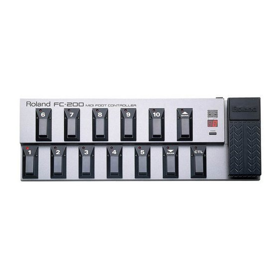
DESCRIPTIONS Front Panel Display Indicators ( 1 to 10, UP/DOWN, CTL ) MODE Button Number Pedals ( 1 to 10 ) BANK Pedals Expression Pedal ( UP/DOWN ) CONTROL Pedal Rear Panel AC Adaptor Jack POWER Switch Cord Hook MODE Jack MIDI Connectors ( IN/OUT ) Foot Switch / Expression... -
Page 7: How To Use The Fc-200
HOW TO USE THE FC-200 The FC-200 offers the four modes described below. Each of these modes provides its own unique features, so choose the mode according to what you wish to do. * See “SWITCHING MODES” (p. 10) for an explanation of how to choose a mode. -
Page 8: Making The Connections
* Sshould the FC-200 tend to rock a little when placed on the floor, turn the two adjusters on the unit’s bottom until you have it in a stand Loading Batteries The FC-200 is not loaded with batteries when purchased. -
Page 9: Switching On The Power
SWITCHING ON THE POWER First, check that you are connected properly with the external MIDI instrument. Then set the power switch on the FC-200 to “ON” or “ECONOMY.” * The FC-200 is in the Program Change mode when first switched on. -
Page 10: Switching Modes
SWITCHING MODES You can change the mode using either the MODE button or a foot pedal plugged into the MODE jack (BOSS FS-5U, Optional). Each of these methods — pressing the button or stepping on the foot pedal — makes the mode change in a different way. When the MODE Button is Pressed Program Change Mode Control Change Mode... -
Page 11: Program Change Mode
PROGRAM CHANGE MODE This is the mode for sending Program Change messages and Control Change messages. About Program Change Numbers The Program Change numbers (1 to 128) are obtained by adding the Program Change number corresponding to the Bank (0 to 12) to the Program Change number corresponding to the Number (1 to 10). -
Page 12: How To Send Program Change Messages
How to Send Program Change Messages Changing the Bank Each press of a BANK pedal (UP/DOWN) changes the Bank, and the new Bank appears on the display. Press the UP pedal to increase the Bank number and the DOWN pedal to lower it. * Simply changing the Bank does not cause a Program Change message to be sent. -
Page 13: Using The Expression Pedal
The pedal sends an ON 127 (7Fh) message when depressed and an OFF 0 (00h) message when released. * This works just the same as a momentary type Control pedal. When a Roland EV-5 Expression Pedal is Connected: Operating the pedal sends data from 0 (00h) to 127 (7Fh) continuously, depending on the pedal’s function. -
Page 14: Control Change Mode
CONTROL CHANGE MODE This is the mode for sending Control Change messages. In this mode, all the pedals can be used to send Control Change messages. You should use this mode at times when you want to send a lot of Control Change messages. Controller Numbers of the Pedals The chart below shows the Controller Number settings. -
Page 15: Using The Foot Switch/Expression Pedal Jacks
The pedal sends an ON 127 (7Fh) message when depressed and an OFF 0 (00h) message when released. * This works just the same as a momentary type Control pedal. When a Roland EV-5 Expression Pedal is Connected: Operating the pedal sends data from 0 (00h) to 127 (7Fh) continuously, depending on the pedal’s function. -
Page 16: Note Mode
NOTE MODE This is the mode for sending Note messages. Note Range The following table shows what notes are assigned to the different pedals. * The indicator for the pedal that the note is assigned to lights up. When “C2” is shown on the display, it means that pressing the note “do” (Number pedal 1) sends a “C2”... -
Page 17: Using The Expression Pedal
Operating the expression pedal causes Control Change messages to be sent. Using the Foot Switch/Expression Pedal Jacks When you connect separately available BOSS FS-5U foot switches or Roland EV-5 expression pedals to the FOOT SW/EXP 1, 2, 3, or 4 jacks, the connected pedals will have the same settings as they do for the Program Change mode and Control Change mode. -
Page 18: Exclusive Mode
This mode is for sending System Exclusive (SysEx) messages. This is the mode to use when you wish to use SysEx messages from the FC-200 to operate another instrument. The method of operation depends on the instrument or device that is receiving the SysEx messages. Refer to the manual... -
Page 19: Edit Function
You can use the Edit function to make changes in the factory default settings and store these changes in memory. Changing the settings on the FC-200 to match the other equipment you are using can make this MIDI foot controller even easier to use. - Page 20 If You Want to Abandon the Changes If you decide that you don’t want to save the changed settings in memory, press the MODE button. The settings all return to their values before changes were made, and the FC-200 returns to its normal state of operation.
-
Page 21: Parameters With Settings That Can Be Changed
PARAMETERS WITH SETTINGS THAT CAN BE CHANGED This section describes those parameters that have settings which can be changed. The explanations here describe functions and what appears on the display. This section uses bold type to indicate factory default settings. If you need information on how to make settings for parameters, see “How to Make Changes”... -
Page 22: Bank Select
* A Bank Select message consists of the controller 0 and 32 Control Change messages. The FC-200 can send Program Change messages from 1 to 128, so a total of 128 programs can be switched. This is the unit’s normal status, whereby Bank Select messages are not sent. -
Page 23: Bank Limit
The chart below shows the programs indicated by the Bank Select and Program Change messages shown above. The Bank pedals and Number pedals on the FC-200 are used to send messages, and the values in parentheses show which pedals to use to choose the corresponding program. -
Page 24: Changing Banks Using The Number Pedals
* If you need information on how to make settings for parameters, see “How to Make Changes” (p. 19). Output of Program Change Messages When Changing Banks: On / Off ] (Bank Output) In the Program Change mode, this sets whether Program Change messages are sent when the Bank is switched. -
Page 25: Controller Number Settings
* If you need information on how to make settings for parameters, see “How to Make Changes” (p. 19). Controller Number Settings: 1 to 31, 33 to 95 This sets the controller numbers that are used when sending Control Change messages. A different controller number is set for each pedal and jack. -
Page 26: Setting For Latch Type Pedal Operation
* If you need information on how to make settings for parameters, see “How to Make Changes” (p. 19). Setting for Latch Type Pedal Operation: On / Off This setting determines whether the pedals work as latch type or momentary type pedals when sending Control Change messages. -
Page 27: Octave Shift Upper Limit Setting
* If you need information on how to make settings for parameters, see “How to Make Changes” (p. 19). Octave Shift Upper Limit Setting: C0 to C6 to C8 ] (High) In the Note mode, a foot pedal connected to FOOT SW/EXP jack 5 can be used to raise the note range an octave at a time. -
Page 28: Mode Jack Loop Setting
* If you need information on how to make settings for parameters, see “How to Make Changes” (p. 19). MODE Jack Loop Setting: 1 / 2 / 3 / 4 ] (Jack Loop) This setting determines how the mode will be switched when using a BOSS FS-5U foot switch connected to the MODE jack to change modes. -
Page 29: About Realtime Messages And Mmc Messages
These messages are used to operate a MIDI sequencer. If you connect a MIDI sequencer that supports Realtime messages, you can use the pedals on the FC-200 to operate the sequencer. * The FC-200 does not output MIDI Clock (F8h) data, so it cannot be used to start or stop some types of MIDI sequencers. -
Page 30: Data Transfer Using Midi
You can use System Exclusive (SysEx) messages to send the FC-200’s settings to another MIDI device. This makes it possible, for instance, to reproduce identical settings on another FC-200, or to save the settings on a MIDI sequencer or some other piece of equipment. -
Page 31: Sending The Data
Sending the Data (the sending FC-200) Switch off the FC-200 that will be used to send the data. While keeping Number pedal “9” depressed, switch the power back on. The indicator for the Control pedal flashes, and [ Press the Control pedal. -
Page 32: Receiving Data (Bulk Load)
For sending data stored on a MIDI sequencer to the FC-200, make the following connections. Receiving Data Make sure the MIDI channel (device ID) for the FC-200 is set to the same MIDI channel as the MIDI sequencer where the data is stored. -
Page 33: About Changing The Batteries
When Batteries Need Changing When the FC-200 is operated only on battery power, the display starts to flash when the batteries begin to run down. This is a warning that means you need to replace the unit’s six size AA batteries with fresh ones as soon as possible. -
Page 34: Using Midi
USING MIDI The FC-200 is equipped with MIDI terminals. Using these terminals to receive data from an external MIDI device makes it possible to switch Program Numbers and change effect settings remotely. About MIDI MIDI is the acronym for “Musical Instrument Digital Interface.” It is an industy-wide standard that allows for data (such as that representing the music played, or for changes in sounds used) to be exchanged among various instruments and computers. -
Page 35: Midi Messages Recognized By The Fc-200
Exclusive messages can be employed to save the settings for Parameter Programs into a sequencer, or for transferring such data to another FC-200. Produced when a keyboard key has been pressed. Produced when a keyboard key has been released. -
Page 36: Midi Implementation Chart
Fold MIDI Device A MIDI Device B Function... Transmitted Recognized Remarks * For detailed information on how MIDI data is handled on this unit, refer to “ROLAND EXCLUSIVE MESSAGES” (p.39) and “MIDI Implementation” (p.41). -
Page 37: Returning Settings To Their Factory Default Values (Initialization)
RETURNING SETTINGS TO THEIR FACTORY DEFAULT VALUES (INITIALIZATION) Initialization lets you return settings that have been edited to the values they had when the FC-200 was shipped from the factory. Switch off the power. While keeping Number pedal “10” depressed, switch the power back on. -
Page 38: If You Think There's A Problem, Check These First38
IF YOU THINK THERE’S A PROBLEM, CHECK THESE FIRST If your FC-200 is not functioning properly, or you suspect there is a problem somewhere, check the following items. If you are still unable to correct the problem, contact your Roland retailer or nearest Roland Service Center. -
Page 39: Roland Exclusive Messages
ROLAND EXCLUSIVE MESSAGES 1. Data Format for Exclusive Messages Roland’s MIDI implementation uses the following data format for all Exclusive messages (type IV): Byte Description Exclusive Status Manufacturer ID (Roland) Device ID Model ID Command ID [BODY] Main data End of exclusive •MIDI status: F0H, F7H... - Page 40 Exclusive one. This fact is inconvenient for devices that support a “soft-thru” function. To maintain compatibility with such devices, Roland has limited the DT1 to 256 bytes so that an excessively long message is sent out in separate 'segments'.
-
Page 41: Midi Implementation
* When FC-200 receives Active Sensing, it measures time intervals between incoming messages. If the subsequent message will not come within 400 msec after the previous one, FC-200 turns off Active Sensing for a period and stops measuring message intervals. - Page 42 Using Roland’s one-way Exclusive message you can transfer data between FC-200 and another device. The model ID of the Exclusive message that can be used in the FC-200 is 72H (FC-200). The Device ID can be set with 00H-0FH. The value is MIDI Channel minus 1.
- Page 43 MODE STATUS (Individual area) Address(H) Size(H) Data(H) Parameter —————————————————————————————— 03 00 00 01 00-03 Mode Status *1 0: Program Mode 03 01 00 01 00-03 Mode Status *2 0: Program Mode *1 Outputs on power-up or when Mode change is made. Also outputs upon receiving Data Request RQ1.
- Page 44 EDIT PARAMETERS (Bulk area) Address(H) Size(H) Data(H) Parameter —————————————————————————————— 10 00 00 1E — Edit Parameters *1 11 00 00 1E — Factory Preset *2 Only the above-mentioned address can be used as the start address. *1 Output during Bulk Dump operation. Also outputs upon receiving Data Request RQ1.
-
Page 45: Midi Implementation Chart
MIDI FOOT CONTROLLER MODEL FC-200 MIDI Implementation Chart Function••• Basic Default Channel Changed Default Mode Messages Altered Note Number True Voice Velocity Note ON Note OFF After Key's Touch Ch's Pitch Bend 0, 32 1 - 31 33 - 95... -
Page 46: Specifications
SPECIFICATIONS FC-200 : MIDI FOOT CONTROLLER Connectors MIDI Connectors (IN / OUT) MODE Jack Foot Switch / Expression (FOOT SW / EXP) Jacks (1to 6) AC Adaptor Jack Controls Number Pedals (1 to 10) BANK Pedals (UP / DOWN) Control (CTL) Pedal... - Page 47 This product complies with the requirements of European Directive 89/336/EEC. FEDERAL COMMUNICATIONS COMMISSION RADIO FREQUENCY INTERFERENCE STATEMENT This equipment has been tested and found to comply with the limits for a Class B digital device, pursuant to Part 15 of the FCC Rules.
- Page 48 00781334 '01-12-A2-61N...
Need help?
Do you have a question about the FC-200 and is the answer not in the manual?
Questions and answers