Dynacord CL 800 Owner's Manual
Linear precision power amp
Hide thumbs
Also See for CL 800:
- Owner's manual (36 pages) ,
- Brochure & specs (72 pages) ,
- Specification sheet (4 pages)
Advertisement
Available languages
Available languages
Advertisement
Chapters

Related Manuals for Dynacord CL 800


Summary of Contents for Dynacord CL 800
- Page 1 OWNER‘S MANUAL BEDIENUNGSANLEITUNG MODE D‘EMPLOI LINEAR PRECISION POWER AMP...
-
Page 2: Table Of Contents
CONTENTS IMPORTANT SAFETY INSTRUCTIONS IMPORTANT SERVICE INSTRUCTIONS DESCRIPTION UNPACKING & WARRANTY INSTALLATION NOTES FRONT VIEW REAR VIEW INPUT A / INPUT B PARALLEL POWER AMP OUTPUT BRIDGED MODE GROUND-LIFT SWITCH MAINS INPUT SPECIFICATIONS BLOCK DIAGRAM DIMENSIONS ������ WICHTIGE SICHERHEITSHINWEISE WICHTIGE SERVICEHINWEISE BESCHREIBUNG AUSPACKEN &... -
Page 3: Important Safety Instructions
IMPORTANT SAFETY INSTRUCTIONS Read these instructions. Keep these instructions. Heed all warnings. Follow all instructions. Do not use this apparatus near water. Clean only with a dry cloth. Do not block any ventilation openings. Install in accordance with the manufacture’s instructions. Do not install near heat sources such as radiators, heat registers, stoves, or other apparatus (including amplifi ers) that produce heat. -
Page 4: Description
Congratulations! With buying a DYNACORD CL-SERIES power amplifi er you have chosen an appli- ance that employs most advanced technology. CL-Series power amps combine outstanding audio performance, highest reliability and operational safety. The audio performance of CL power amps are simply extraordinary. Optimised power supply units em- ploying low-leakage toroidal transformers and the consistent use of Class-H technology provide exten- sive headroom far above the stated nominal output. -
Page 5: Unpacking & Warranty
UNPACKING & WARRANTY Carefully open the packaging and take out the power amplifi er. Next to the power amplifi er itself, the package also includes this owner’s manual, a mains cord and the warranty certifi cate. Keep the original invoice, which states the purchase/delivery date together with the warranty certifi cate at a safe place. INSTALLATION NOTES Generally, installing or mounting power amps should be carried out in a way that guarantees continu- ously unopposed front-to-rear air circulation. -
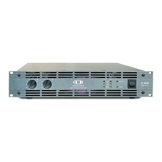
Page 6: Front Panel
Use the POWER switch, located on the front panel’s, right side to switch the appliance’s power on. The soft-start function limits against current inrush peaks on the mains, which in addition prevents the mains line protection switch from activating during power-on. The loudspeaker outputs are activated via relay switching with a delay of approximately 2 seconds to effi ciently attenuate eventual power-on noise. -
Page 7: Rear View
INPUT A / INPUT B CL800 +1.15dBu / 0.88V CL1200 +3.2dBu / 1.12V CL1600 +4.7dBu / 1.33V CL2000 +5.5dBu / 1.46V Although having XLR-type output connectors, some mixing console models provide unbalanced output connection only. When using mixers with unbalanced outputs, bridging PIN1 and PIN3 of the power amp’s input connectors or leaving PIN3 of the cable’s plugs unconnected is necessary. -
Page 8: Power Amp Output
POWER AMP OUTPUT CONNECTORS To prevent short-circuit and/or to protect your speaker systems from being damaged when connecting the cabinets, please make sure to mind the Low- and High channels’ specifi c pin-assignments! If, for example, the subwoofer audio signal is used to feed a tweeter, it is more than likely that this will instantly destroy the HF-driver’s coil. -
Page 9: Mains Operation & Resulting Temperature
MAINS OPERATION & RESULTING TEMPERATURE The following tables allow determining power supply and cabling requirements. The power drawn from the mains network is converted into output power to feed the connected loudspeaker systems and into heat. The difference between power consumption and dispensed power is called power dissipation (Pd). - Page 10 CL1600 idle Max. Output Power @ 8Ω Max. Output Power @ 4Ω 1/3 Max. Output Power @ 4Ω 1/8 Max. Output Power @ 4Ω 1/8 Max. Output Power @ 4Ω (2),(5) 1/8 Max. Output Power @ 4Ω 1/8 Max. Output Power @ 4Ω (3),(5) 1/8 Max.
- Page 11 BEDIENUNGSANLEITUNG LINEAR PRECISION POWER AMP...
-
Page 12: Dimensions
WICHTIGE SICHERHEITSHINWEISE WICHTIGE SERVICEHINWEISE BESCHREIBUNG AUSPACKEN & GARANTIE INSTALLATIONSHINWEISE FRONTSEITE RÜCKSEITE INPUT A / INPUT B PARALLEL ENDSTUFENAUSGÄNGE BRIDGED MODE GROUND-LIFT SCHALTER NETZEINGANG NETZBETRIEB & WÄRMEENTWICKLUNG SPECIFICATIONS / TECHNISCHE DATEN BLOCK DIAGRAM DIMENSIONS / ABMESSUNGEN... -
Page 13: Wichtige Sicherheitshinweise
Lesen Sie diese Anweisungen. Bewahren Sie die Anleitung sorgsam auf. Beachten Sie sämtliche Warnhinweise. Beachten Sie die Anweisungen. Betreiben Sie dieses Gerät nicht in der Nähe von Wasser. Verwenden Sie zur Reinigung ausschließlich ein trockenes Tuch. Achten Sie darauf, dass die Belüftungsöffnungen nicht versperrt sind. Beachten Sie bei der Installation des Geräts die Anweisungen des Herstellers. -
Page 14: Beschreibung
Herzlichen Glückwunsch! Sie haben sich mit einer Endstufe der CL-SERIE von DYNACORD für ein Gerät modernster Technologie entschieden. Die Endstufen der CL-Serie vereinen überragende Audio-Performance mit höchster Zuverlässigkeit und Be- triebssicherheit. Die Übertragungseigenschaften der CL-Endstufen sind hervorragend. Durch optimierte Netzteile mit Die Übertragungseigenschaften der CL-Endstufen sind hervorragend. -
Page 15: Auspacken & Garantie
AUSPACKEN & GARANTIE Öffnen Sie die Verpackung und entnehmen Sie die Endstufe. Zusätzlich zu dieser Bedienungsanleitung liegen dem Gerät ein Netzkabel, und die Garantiekarte bei. Bewahren Sie zur Garantiekarte auch den Kaufbeleg, der den Termin der Übergabe festlegt, auf. INSTALLATIONSHINWEISE Generell sind die Endstufen so aufzustellen oder zu montieren, dass die Luftzufuhr an der Frontseite und die Entlüftung an der Geräterückseite nicht behindert wird. -
Page 16: Frontseite
Mit dem POWER Schalter rechts auf der Frontblende wird das Gerät eingeschaltet. Eine Softstart- POWER Schalter POWER Schalter rechts auf der Frontblende wird das Gerät eingeschaltet. Eine Softstart- Schaltung vermeidet dabei Einschaltstromspitzen auf der Netzleitung. Dadurch wird verhindert, dass der Leitungsschutzschalter des Stromnetzes beim Einschalten der Endstufe anspricht. Die Lautspre- cher werden über die Ausgangsrelais um ca. -
Page 17: Rückseite
INPUT A / INPUT B CL800 +1.15dBu / 0.88V CL1200 +3.2dBu / 1.12V CL1600 +4.7dBu / 1.33V CL2000 +5.5dBu / 1.46V „Durchschleifen“ des Eingangssignals zu weiteren Endstufen vorgesehen. Das Eingangssignal wird dabei direkt auf die Ausgangsbuchsen gelegt, es befi nden sich keine Zwischenverstärker oder andere elektro- nischen Bauteile in diesem Pfad. -
Page 18: Endstufenausgänge
ENDSTUFENAUSGANGSBUCHSEN Bitte beachten Sie beim Anschluss der Lautsprecher unbedingt die Beschaltung für Low- und High- Kanal um Kurzschlüsse oder Lautsprecherdefekte zu vermeiden! Wird z.B. ein Hochtontreiber mit einem Subwoofersignal angesteuert, kann es zu einer sofortigen Zerstörung der Schwingspule im Hochtontreiber kommen. Warnung: Das Symbol “... -
Page 19: Netzbetrieb & Wärmeentwicklung
NETZBETRIEB & WÄRMEENTWICKLUNG IN DER ENDSTUFE Mit Hilfe der folgenden Tabellen können die Anforderungen für Stromversorgung und Zuleitungen bestimmt werden. Die vom Stromnetz aufgenommene Leistung wird in Ausgangsleistung für die Lautsprecher und in Wärme umgewandelt. Die Differenz aus aufgenommener Leistung und abgegebener Leistung nennt man Verlustleistung ( ). - Page 20 CL1600 idle Max. Output Power @ 8Ω Max. Output Power @ 4Ω 1/3 Max. Output Power @ 4Ω 1/8 Max. Output Power @ 4Ω 1/8 Max. Output Power @ 4Ω (2),(5) 1/8 Max. Output Power @ 4Ω 1/8 Max. Output Power @ 4Ω (3),(5) 1/8 Max.
- Page 21 MODE D‘EMPLOI LINEAR PRECISION POWER AMP...
- Page 22 IMPORTANTES INFORMATIONS DE SÉCURITÉ INSTRUCTIONS DE RÉPARATION IMPORTANTES ... DESCRIPTION DÉBALLAGE ET GARANTIE REMARQUES SUR L’INSTALLATION FACE AVANT PANNEAU ARRIÈRE INPUT A / INPUT B PARALLEL SORTIE DE AMPLI DE PUISSANCE GROUND-LIFT ENTRÉE SECTEUR SECTEUR ET TEMPÉRATURE RÉSULTANTE SPECIFICATIONS BLOCK DIAGRAM DIMENSIONS...
-
Page 23: Importantes Informations De Sécurité
INSTRUCTIONS DE SÉCURITÉ IMPORTANTES Veuillez lire ces instructions. Conservez ces instructions. Respectez toutes les consignes de sécurité. Suivez scrupuleusement toutes les instructions. N’utilisez pas cet appareil près d’un point d’eau. Utilisez uniquement un chiffon sec pour le nettoyer. N’obstruez aucune des ouïes de ventilation. Installez-le en respectant les instructions du fabricant. Ne l’installez pas près de sources de chaleur tels que radiateurs, panneaux chauffants, étuves, ou autres appareils produisant de la chaleur (dont les amplifi cateurs). -
Page 24: Description
électrique est bien moindre que celle d’un ampli de Classe A-B. Les amplifi cateurs de puissance DYNACORD CL-SERIES ont été conçus pour satisfaire aux conditions de tournée les plus puissance DYNACORD CL-SERIES ont été conçus pour satisfaire aux conditions de tournée les plus exigeantes. -
Page 25: Déballage Et Garantie
DÉBALLAGE ET GARANTIE Ouvrez avec précautions le carton d’emballage et sortez votre amplifi cateur de puissance. En plus de l’amplifi cateur de puissance lui-même, le carton contient également le présent mode d’emploi, le cordon secteur et le certifi cat de garantie. Conservez en lieu sûr, l’original de la facture, qui mentionne la date d’achat et de livraison, ainsi que le certifi cat de garantie. -
Page 26: Face Avant
Utilisez l’interrupteur secteur, situé en face avant, du côté droit, pour mettre l’appareil sous tension. La fonction Soft-Start élimine les crêtes provoquées par l’appel de courant à l’allumage, ce qui par la même évite que le commutateur de protection secteur ne s’enclenche lors de la mise sous tension. Les sorties haut-parleur sont activées via la commutation d’un relais avec une temporisation d’environ 2 secondes de façon à... -
Page 27: Panneau Arrière
INPUT A / INPUT B CL800 +1.15dBu / 0.88V CL1200 +3.2dBu / 1.12V CL1600 +4.7dBu / 1.33V CL2000 +5.5dBu / 1.46V sont prévus pour un branchement „transparent“ des signaux d’entrée vers d’autres amplifi cateurs de puissance. Le signal d’entrée est directement dirigé vers ces connecteurs de sortie. Il ne s’agit pas de répétiteurs ou autres composants électroniques intégrés dans le trajet du signal. -
Page 28: Sortie De Ampli De Puissance
CONNECTEURS DE SORTIE DE AMPLI DE PUISSANCE Si, par exemple, le signal audio du subwoofer est raccordé à un tweeter, il est à peu près sûr que ceci détruira instantanément le bobinage du HP des aigus. (HF-driver’s coil). ATTENTION : Les bornes de sortie haut-parleur sont marquées d‘un symbole „... -
Page 29: Secteur Et Température Résultante
ALIMENTATION SECTEUR ET TEMPÉRATURE RÉSULTANTE Le tableau suivant indique les normes d’alimentation secteur et de câblage. Le courant d’alimentation secteur est converti en puissance de sortie pour alimenter les haut-parleurs connectés et en chaleur. La différence entre la consommation électrique et la puissance dispensée est appelée puissance dissipée (Pd). - Page 30 CL1600 idle Max. Output Power @ 8Ω Max. Output Power @ 4Ω 1/3 Max. Output Power @ 4Ω 1/8 Max. Output Power @ 4Ω 1/8 Max. Output Power @ 4Ω (2),(5) 1/8 Max. Output Power @ 4Ω 1/8 Max. Output Power @ 4Ω (3),(5) 1/8 Max.
-
Page 31: Specifications
- Amplifi er at rated conditions, both channels driven, 8Ω load, unless otherwise specifi ed. Load Impedance 2 Ω Max. Midband 600W Output Power THD = 1%, 1kHz , Dual Channel Rated Output Power THD < 0,1%, 20Hz … 20kHz Max. -
Page 32: Block Diagram
BLOCK DIAGRAM... -
Page 33: Abmessungen
ABMESSUNGEN / DIMENSIONS ABMESSUNGEN / DIMENSIONS (in mm) - Page 34 NOTES...
- Page 35 NOTES...
- Page 36 Telex Communications Inc., 12000 Portland Ave. South, Burnsville, MN 55337, Phone: +1 952-884-4051, FAX: +1 952-884-0043 Germany EVI AUDIO GmbH, Hirschberger Ring 45, D 94315, Straubing, Germany Phone: 49 9421-706 0, FAX: 49 9421-706 265 Subject to change without prior notice. Printed in Germany 07/03/2006 / D 366 197 www.dynacord.de...
Need help?
Do you have a question about the CL 800 and is the answer not in the manual?
Questions and answers