Table of Contents
Advertisement
Quick Links
All manuals and user guides at all-guides.com
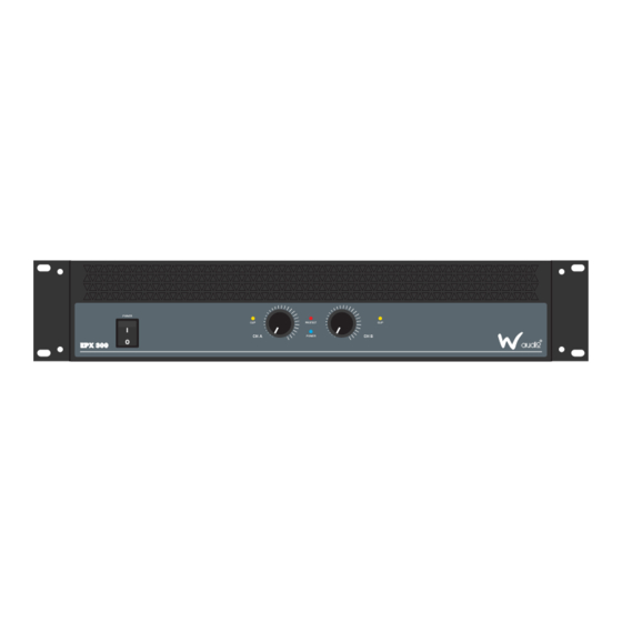
EPX Series
Power Amplifiers
User Manual
POWER
CLIP
I
CH A
O
POWER
CLIP
I
CH A
O
POWER
CLIP
I
CH A
O
POWER
CLIP
I
CH A
O
POWER
CLIP
I
CH A
O
Order codes:
AMP24 - EPX 300
AMP25 - EPX 500
AMP26 - EPX 800
AMP27 - EPX 1200
AMP28 - EPX 2200
PROTECT
CLIP
POWER
CH B
PROTECT
CLIP
POWER
CH B
PROTECT
CLIP
POWER
CH B
ST
BR
PR
CLIP
PROTECT
POWER
CH B
ST
BR
PR
CLIP
PROTECT
POWER
CH B
Advertisement
Table of Contents

Subscribe to Our Youtube Channel
Related Manuals for W Audio EPX Series


Summary of Contents for W Audio EPX Series
- Page 1 All manuals and user guides at all-guides.com EPX Series Power Amplifiers User Manual POWER CLIP PROTECT CLIP CH A POWER CH B POWER PROTECT CLIP CLIP CH A POWER CH B POWER CLIP PROTECT CLIP CH A POWER CH B...
-
Page 2: Safety Advice
• Only use the equipment indoors. reached room temperature. • Do not expose to flammable sources, liquids or gases. • If the product fails to function correctly, discontinue use • Always disconnect the power from the mains when immediately. Pack securely (preferably in the original equipment is not in use or before cleaning! Only handle packing material), and return to your dealer for service. the power cable by the plug. Never pull out the plug by • Only use fuses of same type and rating. pulling the power cable. • Repairs, servicing and power connection must only be • Make sure that the available voltage carried out by a qualified technician. THIS UNIT CONTAINS is between 220V/240V. NO USER SERVICEABLE PARTS. • WARRANTY: One year from date of purchase. OPERATING DETERMINATIONS If this equipment is operated in any other way, than those described in this manual, the product may suffer damage and the warranty becomes void. Incorrect operation may lead to danger e.g: short-circuit, burns and electric shocks etc. In case of malfunction this unit should be returned for service or inspection. Do not endanger your own safety and the safety of others! Incorrect installation or use can cause serious damage to people and/or property. EPX Series Power Amplifiers User Manual www.prolight.co.uk... -
Page 3: Product Overview
& AC power supply fuse LED indicators Power, protect & clip Power, protect, clip, stereo, parallel & bridge Inputs: 2 x XLR sockets, 2 x 1/4” jack sockets Inputs: 2 x phono sockets, 2 x 1/4” jack sockets Outputs: 2 x locking speaker connectors, Connectors Outputs: 2 x locking speaker connectors, 2 x binding posts 2 x binding posts, 1 x locking speaker bridge connector Cooling system Low-noise cooling fans, variable speed fan Power supply AC240V/50Hz Dimensions (H x W x D) 87 x 481 x 297mm 87 x 481 x 297mm 87 x 481 x 297mm 87 x 481 x 450mm 87 x 481 x 450mm Weight 9.5kg 10kg 10.5kg 18kg 21kg Order code AMP24 AMP25 AMP26 AMP27 AMP28 EPX Series Power Amplifiers User Manual www.prolight.co.uk... - Page 4 All manuals and user guides at all-guides.com Product overview EPX 300, EPX 500 & EPX 800 dimensions 426mm 481mm EPX 1200 & EPX 2200 dimensions 426mm 481mm EPX Series Power Amplifiers User Manual www.prolight.co.uk...
-
Page 5: Technical Specifications
Operating temperature range 0-40°C. This product is not intended for use other than stated. LIFT 01 - ¼” jack inputs - These inputs allow you to connect 04 - Power cable socket - This is where you connect the ¼”unbalanced jack plugs detachable power cable. Connect the other end to a 240V AC outlet. 02 - Phono inputs - These inputs allow you to connect unbalanced phono plugs 05 - Ground lift switch - This switch allows the signal ground or chassis ground to be separated in case of a ground 03 - There are three ways of connecting your speakers: conflict. For the highest safety of the equipment, it is Locking speaker connectors, ¼” jack or binding posts. recommended to keep the “ground lift switch” in the The connectors are wired in parallel. (e.g. Channel 1 GND position. In case of a ground conflict please set the binding post, jack and locking speaker connectors are in ground lift switch to GND LIFT. parallel and the same for channel 2). EPX Series Power Amplifiers User Manual www.prolight.co.uk... - Page 6 CH A POWER CH B 01 - Clip LEDs - These LEDs flash red to indicate when the 03 - Power LED - This LED illuminates when the amplifier output of the amplifier has reached the maximum, and is is switched on right on the edge of clipping. Clipping is bad for speakers 04 - Protect LED - If this LED is illuminated during operation, and should be avoided. It is okay if the LED blinks one of the protection circuits is active. Please take the occasionally. It means that the transient peaks of the amplifier out of operation and have it tested music are just hitting the full output of the amplifier. 05 - Stereo LED - This illuminates in stereo mode 02 - Gain control - These two knobs control the levels of 06 - Bridged LED - This illuminates in bridged mode Channels 1 and 2. Usually, these controls are set all the 07 - Parallel LED - This LED illuminates in parallel mode way up. You might turn them down slightly if you have high-efficiency speakers. Also, you could use them to 08 - Power switch - Press this switch to start the operation control the level of line-level sources such as a CD player connected directly to the amplifier without a pre-amplifier or mixer. After you have set the levels for the mixer (or other signal source), adjust the Level controls on the amplifier as the final adjustment to set the overall volume for the system. In stereo and mono mode, use both level controls to control the levels going to each speaker. In bridged mode, turn the channel 2 level control down, and just use the channel 1 control. EPX Series Power Amplifiers User Manual www.prolight.co.uk...
- Page 7 GND position. In case of a ground conflict please set When the amplifier is used in bridged mono mode use the ground lift switch to GND LIFT. either the output bridged locking speaker connectors or the two red binding posts. 08 - These balanced XLR outputs can be used to loop through the signal to additional power amplifiers. 04 - Locking power socket - This is where you connect the detachable locking power cable. Connect the other end 09 - Crossover: For normal operation set the mode switch to to a 240V AC outlet. Bypass. Low/High Pass Mode: When using the “Low/ High Pass Mode”, the amplifier can be configured for 05 - Amp mode - This switch determines the input signal High Pass or Low Pass operation. routing within the amplifier. For most applications stereo will be used. Stereo: This is the normal mode for amplifying stereo signals. It accepts left and right inputs and routes them to the left and right outputs. Parallel: This mode is used when you want to send mono signals to both outputs. It accepts a single input into channel 1 and routes it to both the channel 1 and channel 2 outputs. Each channels level control adjusts the gain for each channel. Bridge: This mode accepts a single input into channel 1 and uses both amplifier outputs to double the power to one speaker output. Use channel 1 level control to adjust the gain. Turn channel 2 level control to minimum. EPX Series Power Amplifiers User Manual www.prolight.co.uk...
-
Page 8: Rack Installation
All manuals and user guides at all-guides.com Operating instructions Rack installation The EP Series is built for 19” racks. The rack you use should be a ‘double door rack’ where you can open the front and rear panel. When mounting the amplifier into the rack, please make sure that there is enough space around the amplifier. Be careful when mounting the amplifier into the rack. Put the heaviest products into the lower part of the rack. Be aware that fastening the amplifier with four screws on the front panel is not enough. If the racks are being transported or used for mobile use, additionally fasten the products by connecting the rear brackets with the side or ground bars of the rack. In this way, the amplifier cannot be pushed backwards. The front panel is not designed to absorb acceleration forces occuring during transportation. Inputs Short cables runs improve the sound quality remarkably. Input cables should be short and direct, since high frequencies will mostly be absorbed if the cables are unnecessarily long. Besides that a longer cable may lead to humming and noise problems. If the cable runs are unavoidable, you should use balanced cables. Outputs The high damping factor of your amplifier supplies a clear sound reproduction. Unnecessarily long and thin cables will influence the damping factor and thus the low frequencies in a negative way. In order to safeguard good sound quality, the damping factor should lie around 50. The longer a cable has to be the thicker it should be. Connect your speaker systems via the locking speaker connectors or the Bannana/Screw combination (red+, black-) Connection to the mains Connect the amplifier only after having made sure that the correct voltage (240V) is supplied and that the ground cable is earthed. This product falls under Class 1. Do not detach the ground cable. EPX Series Power Amplifiers User Manual www.prolight.co.uk... -
Page 9: Operation
Problem Chart Problem Cause Solution No power The power cable is not connected Check the power cable and any extension cables The power cable of the respective product is Check the power cable and if the plugs are properly not connected correctly or not at all. connected with the sockets No sound The connection socket or the plug is dirty Clean the socket and/or the plug Noise The input signal is too strong Reduce the input signal via the gain control Fan does not work, The power cable is not connected Connect the power cable LEDs do not light up Switch amplifier off and have the product checked DC voltage on input by a service technician Amplifier overheats due to obstruction Clean the fan grill Protect LED lights up permanently Impedance of speakers too low Ensure minimum 4Ω load Short circuit in speaker connection Check speakers and connections or in speakers EPX Series Power Amplifiers User Manual www.prolight.co.uk... - Page 10 CAUTION! - DANGER TO LIFE DISCONNECT FROM THE MAINS BEFORE STARTING MAINTENANCE OPERATION Cleaning and Maintenance We recommend a frequent cleaning of the product. Please use a soft lint free and moistened cloth. Never use alcohol or solvents. There are no serviceable parts inside the product except for the fuse. Maintenance and service operations are only to be carried out by authorised dealers. Replacing the fuse Only replace the fuse with a fuse of the same type and rating. Before replacing the fuse, unplug the mains cable. Procedure: Step 1: Open fuse holder on the rear panel with a screwdriver. Step 2: Remove the old fuse from the fuse holder. Step 3: Install the new fuse in the fuse holder. Step 4: Replace the fuse holder in the housing. Should you need any spare parts, please use genuine parts. Should you have any further questions, please contact your dealer. EPX Series Power Amplifiers User Manual www.prolight.co.uk...
-
Page 11: Weee Notice
WEEE notice Correct Disposal of this Product (Waste Electrical & Electronic Equipment) (Applicable in the European Union and other European countries with separate collection systems) This marking shown on the product or its literature, indicates that it should not be disposed of with other household wastes at the end of its working life. To prevent possible harm to the environment or human health from uncontrolled waste disposal, please separate this from other types of wastes and recycle it responsibly to promote the sustainable reuse of material resources. Household users should contact either the retailer where they purchased this product, or their local government office, for details of where and how they can take this item for environmentally safe recycling. Business users should contact their supplier and check the terms and conditions of the purchase contract. This product should not be mixed with other commercial wastes for disposal. EPX Series Power Amplifiers User Manual www.prolight.co.uk... - Page 12 All manuals and user guides at all-guides.com EPX Series Power Amplifiers User Manual www.prolight.co.uk...
Need help?
Do you have a question about the EPX Series and is the answer not in the manual?
Questions and answers