Table of Contents
Advertisement
Advertisement
Table of Contents

Related Manuals for LONCIN LC2V80FD


Summary of Contents for LONCIN LC2V80FD
- Page 1 LC2V80FD Maintenance Manual LONCIN MOTOR CO., LTD.
- Page 2 SAFETY INFORMATION SAFETY INFORMATION Before operating and maintaining the engine, and maintaining the engine, machine is stopped for a moment, it would be machine is stopped for a moment, it would be please carefully read and understand the please carefully read and understand the hot.
-
Page 3: Table Of Contents
Contents Part I Technical Specifications 1-1 Introduction of engine ............................ 1 1-2 Technical parameters ............................. 3 1-3 Model installation dimensional drawing ......................4 1-4 P.T.O dimensional drawing ........................... 7 1-5 Electric wiring diagram ..........................9 Part II Repair Instructions 2-1 Maintenance precautions ..........................10 2-2 Marking position of machine No. - Page 4 Contents 4-10 Check the cylinder pressure ........................33 4-11 Detection of spark ............................33 Part V Disassembly & Repair 5-1 Precautions on disassembly/assembly ......................34 5-1-1 Disassembly .............................. 34 5-1-2 Assembly ..............................34 5-2 Disassembly and maintenance of engine...................... 35 5-2-1 Air filter ..............................
-
Page 5: Part I Technical Specifications
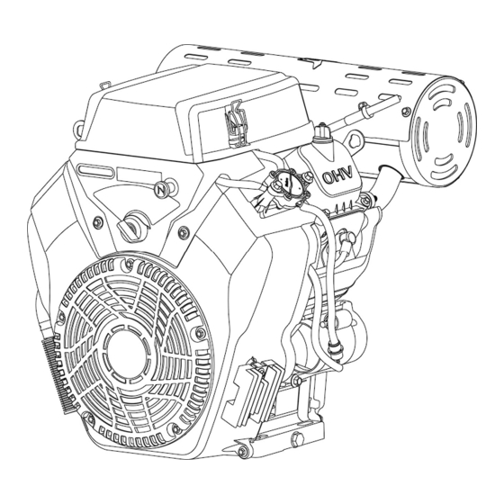
Part I Technical Specifications 1-1 Introduction of engine Silencer Air filter Fuel pump Choke-valve handles Spark plug cap Engine switch Secondary oil filter Throttle handle Oil drain bolt Oil condenser - 1 -... - Page 6 Part I Technical Specifications Air filter - protect the engine through filtering dusts and impurities in the air. Spark plug - input high voltage at ignition coil to the engine combustor, generate spark through air discharge between electrodes and introduce combustion of mixed gases. Silencer - a device to prevent the transmission of engine sound and reduce the noise of exhaust system.
-
Page 7: Technical Parameters
Part I Technical Specifications 1-2 Technical parameters Single-engine Power Unit Power Double-cylinder, four-stroke-cycle, forced-air cooling and overhead Type of Engine valve Air displacement 764ml(80mmX76mm) (diameter of cylinder × stroke) Maximum power (kW/3600rpm) Maximum torque (N·m) 52/2800 Corresponding rotating speed (rpm) Fuel consumption rate ≤... -
Page 8: Model Installation Dimensional Drawing
Part I Technical Specifications 1-3 Model installation dimensional drawing Unit power - 4 -... - Page 9 Part I Technical Specifications Single-engine power - 5 -...
- Page 10 Part I Technical Specifications Crankcase cover interface dimensions Mounting size of base - 6 -...
-
Page 11: Dimensional Drawing
Part I Technical Specifications 1-4 P.T.O dimensional drawing A 轴/Type A B轴/Type B - 7 -... - Page 12 Part I Technical Specifications C轴/Type C - 8 -...
-
Page 13: Electric Wiring Diagram
Part I Technical Specifications 1-5 Electric wiring diagram - 9 -... -
Page 14: Part Ii Repair Instructions
1. Use pure LONCIN parts or the specified parts and 1. Use pure LONCIN parts or the specified parts and during assembly. -
Page 15: Marking Position Of Machine No
P.: the page shall be referred to. 2-2 Marking position of machine No. Machine No. is marked on the crankcase as shown in the figure below. When LONCIN dealers require correct parts during maintenance, the machine number is used to check the engine or to order parts. -
Page 16: Maintenance Standards
Part II Repair Instructions 2-3 Maintenance standards Unspecified unit: mm LC2V80FD Parts Item Standard Maintenance limit - Engine Compression pressure (kgf/cm 11-13 Air cylinder Inner diameter of cylinder liner 80-80.01 80.15 Outer diameter of skirt 79.965-79.975 79.755 Clearance to the air cylinder 0.025~0.045... -
Page 17: Torque Parameters Of Fasteners
Part II Repair Instructions Outer diameter (bearing position) 15.966~15.984 15.916 Crankcase cover Inner diameter of camshaft hole 16.068 16~16.018 - Spark plug Electrode clearance 0.7-0.8 - Spark plug cap Resistance 10k Ω - Resistance value Primary side 1-1.4Ω - Ignition coil Resistance value Secondary side 6.2-7.6Ω... - Page 18 Part II Repair Instructions (2) Standard torque parameters Fastening Parts Specification of Thread Torque (N.m) 5 mm Bolt and nut 6 mm Bolt and nut 8-12 Bolt and nut 8 mm Bolt and nut 20-28 10 mm Bolt and nut 35-40 12 mm Bolt and nut 50-60...
-
Page 19: Part Iii Maintenance
(1) Maintenance intervals shall be shortened when it is used in a place full of dusts. (2) Unless users have professional repair tools and maintenance skills, or these projects shall be assisted and maintained by franchised dealers of LONCIN. (3) Only replace foam and paper filter cartridge Under circumstances of frequent use, long-term use can only be guaranteed through maintenance with correct intervals specified above. -
Page 20: Change Engine Oil
With replacement of secondary oil filter: 1.8 L To make the engine achieve its ideal operating effect, it is suggested to use the qualified and dedicated engine oil of LONCIN. Recommended engine oil: 4-stroke gasoline engine oil. API-classified SE, SF or equivalent to SG grade’s SAE 10W-30. - Page 21 Part III Maintenance Part III Maintenance The waste oil contains hazardous substances which may caus The waste oil contains hazardous substances which may cause skin cancer for long-term exposure to the waste oil. term exposure to the waste oil. After exposing to the waste oil, please thoroughly clean your hands with soap and clear water as soon as possible. After exposing to the waste oil, please thoroughly clean your hands with soap and clear water as soon as possible.
-
Page 22: Maintenance Of Air Filter
Part III Maintenance 3-3 Maintenance of air filter Air inflow will be affected and the power of engine will be reduced after the filter element of the air filter gets dirty. If the operation area is full of dust, the maintenance shall be conducted more frequently. No filter cartridge or use of damaged filter cartridge may cause dusts to enter the engine and Caution then cause the rapid erosion of the engine. -
Page 23: Maintenance Of Silencer
Part III Maintenance Part III Maintenance 3-4 Maintenance of silencer During the long-term use of silencer, it may cause term use of silencer, it may cause carbon deposition and bring about severe influence carbon deposition and bring about severe influence to the exhaust system. -
Page 24: Maintenance Of Spark Plug
Part III Maintenance 3-5 Maintenance of spark plug Recommended spark-plug types: RC12YC or equivalent spark plugs. The replacement of spark plug has the following advantages: Spark plug cap Guarantee the continuous spark; start with more reliability; better fuel conservation Note The use of spark plug with incorrect models and heat values may reduce the engine performance or damage the engine. -
Page 25: Adjustment Of Valve Clearance
Part III Maintenance spark plug mounting thread disorder inside the engine. 6. Install the spark plug cap onto the spark plug. Thickness gauge 3-6 Adjustment of valve clearance The check and adjustment of valve clearance must be conducted when the engine is cold. Seen from the output end of the engine, firstly adjust the valve clearance of the left cylinder, then rotate anticlockwise the crankshaft to 270°... -
Page 26: Adjustment Of Speed Regulator
Part III Maintenance Standard engine idle rotation speed: 1,800±150 rpm 3-8 Adjustment of speed regulator Mechanical speed regulating engine Throttle pull Fuel control assy. Speed-regulating spring Accelerator, rope Throttle control handles Speed-regulating support Speed-regulating arm 1. Loosen the fastening nut of speed-regulating arm. 2. -
Page 27: Storage Of Engine
Part III Maintenance 2. The control module controls the stepper motor 3. Stepper motor controls throttle opening of carburetor 4. Ensure fixed speed, high speed and low speed Step motor Throttle opening procedure Control Fixed speed Controller Pass 3-9 Storage of engine After it is shut down, cool the engine down for at least half an hour prior to cleaning. - Page 28 Part III Maintenance Re-install the spark plug. Rotate the engine slowly till you feel the resistance. The inlet and exhaust valves are both in the closed status, which prevent moisture entering the cylinder head. Cover an anti-dust coating to the engine and place it in a ventilated dry place. During the storage, charge the battery every month.
-
Page 29: Part Iv Faults Diagnosis
Part IV Faults Diagnosis 4-1 Difficulty of engine in starting Excessive engine oil (Stop for several minutes before restarting) Insufficient fuel (Add fuel oil into the fuel tank) Fuel system Fuel filter screen blocked (Clean fuel filter screen) Fault or improper adjustment of carburetor (Refer to Section 5-2-4) Air cleaner dirty (Clean or replace) -
Page 30: Underpower Of Engine
Part IV Faults Diagnosis 4-2 Underpower of engine Poor fuel quality (Use new fuel of designated quality) Fuel filter blocked Fuel system (Clean fuel filter) Fault or improper adjustment of carburetor (Refer to Section 5-2-4) Choke valve not fully opened (Open it to the maximum) Air filter dirty (Clean air filter) -
Page 31: Rotating Speed Instability Of Engine
Part IV Faults Diagnosis 4-3 Rotating speed instability of engine Fuel is insufficient/of poor quality/polluted (Use new fuel oil of specified quality) Fuel filter blocked Fuel system (Clean fuel filter) Carburetor blocked (Refer to Section 5-2-4) Spark plug blocked Rotational (Refer to Section 3-5) speed Ignition system... -
Page 32: Abnormal Exhaust Colors Of Engine
Part IV Faults Diagnosis 4-4 Abnormal exhaust colors of engine Air filter excessively dirty (Clean air filter) Fault of carburetor Black (Refer to Section 5-2-4) Overloaded (Alleviate load) Low temperature of engine (Normal starting) Abnormal White exhaust color Water contained in fuel (Use new fuel oil of specified quality) Engine oil contained in fuel (Use new fuel oil of specified quality) -
Page 33: Engine Is Easily To Be Flameout
Part IV Faults Diagnosis 4-5 Engine is easily to be flameout Spark plug dirty or wet (Refer to Section 3-5) Fuel level of carburetor too high Engine is (Adjust the height of the float of the carburetor) easily to be flameout Improper idle speed adjustment (Refer to Section 3-7) -
Page 34: Overheat Of Engine
Part IV Faults Diagnosis 4-7 Overheat of engine Wrong ignition time (Adjust ignition time) Engine oil insufficient or polluted (Add or replace engine oil) Silencer blocked (Refer to Section 3-4) Overheat of Ring flutter of cylinder and crankcase due to engine failure of piston ring causing (Replace worn parts) -
Page 35: Abnormal Noises Of Engine
Part IV Faults Diagnosis 4-8 Abnormal noises of engine Wear of piston and piston ring (Replace piston and piston ring) Wear of connecting-rod, piston pin and pin hole (Replace worn parts) Rattle Wear of crankshaft bearing (Replace wore parts) Breakage of piston ring (Replace piston ring) Excessive carbon deposition in combustor (Remove carbon deposition) -
Page 36: Fault Of Electric Starting System
Part IV Faults Diagnosis 4-9 Fault of electric starting system Battery fault (Charge or replace) Short circuit or broken circuit of lead wire or connecting plug No click sound (Repair or replace) Fuse burn-out (Replace) Dose electric relay Fault of engine switch (switch) have (Repair or replace) -
Page 37: Check The Cylinder Pressure
Part IV Faults Diagnosis 4-10 Check the cylinder pressure 1) Remove the spark plug cap and spark plug. 2) Install the pressure gauge onto the spark plug hole 3) Start the engine for several times to measure the compression pressure. Pressure Cylinder gauge... -
Page 38: Part V Disassembly & Repair
Chapter V Disassembly & Repair 5-1 Precautions on disassembly/assembly 5-1-1 Disassembly 1. Get familiar with the constitution and operating principle of the machine prior to disassembly, which is the precondition for correct disassembly. 2. Not disassemble those without the need. Blind disassembly will not only increase workload of repair but also damage the original good coordinating relation and precision among parts so as to cause new hidden faults. -
Page 39: Disassembly And Maintenance Of Engine
Chapter V Disassembly & Repair 5-2 Disassembly and maintenance of engine 5-2-1 Air filter Inner Air filter connecting pipe filter cartridge Air filter seat Assembly: clean inside and replace tubes Disassembly/assembly: clean with aging or crack. the inside with compressed air and then install. -
Page 40: Silencer
Chapter V Disassembly & Repair 5-2-2 Silencer Silencer Hexagon nut M8 (4) Assembly: Torque: (27 ~ 30) N•m Tap with plastic hammer to remove carbon deposition and Flange bolt M8 × 16 (2) then install. Torque: (22 ~ 26) N•m Gasket exhaust port Assembly... -
Page 41: Fan Cover - Starting Control Switch
Chapter V Disassembly & Repair 5-2-3 Fan cover - starting control switch Harness of starting control switch Plate,fan cover Starting control switch Oil pipe Assembly: check if the pipe is aged or cracked before installation. Fan cover part Voltage regulating rectifier Radiator part Assembly... - Page 42 Chapter V Disassembly & Repair b. Check Engine switch Check the conductivity of switch terminal at each location of the switch. 1. When the switch is under the Off status, connect the orange terminal to the switch (at the surface of lock nut of the switch);...
- Page 43 Chapter V Disassembly & Repair Voltage regulating rectifier 120W 2900rpm~3900rpm, Module output voltage:DC13.8±0.5V; It should carry rated load 120W ,voltage should more than DC13V; Current limiting protection: when the load current is greater than 9A, voltage stabilizer into protection state, but maintain the output 12A current; 180W 2900rpm~3900rpm, Module output voltage:13.8±0.5V;...
-
Page 44: Carburetor
Chapter V Disassembly & Repair 5-2-4 Carburetor Warning The gasoline is flammable and explosive. The fuel stop valve must be closed before repairing the carburetor and drain the fuel in the carburetor. Air filter seat Assembly Dirty, damaged or deformed one shall be cleaned or replaced immediately. - Page 45 Chapter V Disassembly & Repair Disassembly/assembly Note: clean the carburetor prior to installation Idle jet Assembly: Clean thoroughly with compressed air Idle mixture adjusting screw before installation and slightly lubricate the O-ring. O-ring Assembly: Check the wear at the front before installation.
- Page 46 Chapter V Disassembly & Repair Chapter V Disassembly & Repair c. Check of float height Place carburetor according to the figure and push in the float Place carburetor according to the figure and push in the float with fingers. When the float valve touches the float seat and When the float valve touches the float seat and the spring doesn’t compress, measure the dimensions between float and doesn’t compress, measure the dimensions between float and...
-
Page 47: Speed-Regulating Mechanism
Chapter V Disassembly & Repair 5-2-5 Speed-regulating mechanism Speed-regulating support Choke-valve Assembly: stem Adjust the speed regulator Fuel control assy. during assembly. Choke-valve handle Throttle lever Speed-regulating spring Nut: M6 Accelerator, rope Split pin Needle Assembly: insert the bearing split pin into the Throttle control speed-regulating arm combination... -
Page 48: Flywheel And Ignition Coil
Chapter V Disassembly & Repair Chapter V Disassembly & Repair 5-2-6 Flywheel and ignition coil a. Disassembly/assembly Starting engine part Starting engine part Flange bolt M8 × 95 Torque: (22 ~ 28) N•m Ignition coil Ignition coil Assembly: Assembly: Prior Prior installation, check if the insulation is... - Page 49 Chapter V Disassembly & Repair b.Adjustment of clearance between ignition coils When re-assembling the ignition coil, adjust the clearance between ignition coil and flywheel. 1) Slightly screw the mounting bolt of ignition coil. 2) As shown in the figure, insert the thickness gauge into the clearance of ignition coil and flywheel, or Insert the paper of the same thickness on the circle of the flywheel.
- Page 50 Chapter V Disassembly & Repair c. Spark plug cap Connect the ohm gauge to the two ends of the spark plug cap to measure the resistance of spark plug cap. Resistance value 9-11 KΩ Replace the spark plug cap if the resistance value doesn’t meet specifications.
-
Page 51: Cylinder Head And Valve
Chapter V Disassembly & Repair 5-2-7 Cylinder head and valve Disassembly/assembly Flange bolt M10 × 65 Flange bolt M6 × 25 Torque: (50 ~ 55) N•m Assembly/disassembly: Torque: (8 ~ 12) N•m Loosening and fastening of bolt must be done by Oil stopper way of crossing, especially when fastening the bolt. - Page 52 Chapter V Disassembly & Repair Valve rocker arm Assembly: Check if the contact surface of Nut M6 rocker arm, central hole or valve lifter is worn prior to installation. Torque: ( 12 ~ 16) N•m Tappet combination Assembly: Confirm the wear of two ends and upright of lifter body, and then pass through the guide hole and place into the crankcase...
- Page 53 Chapter V Disassembly & Repair Free length of the valve spring Measure the free length of valve spring. Standard Maintenance Limit 39.5~40.5 mm 39 mm Replace the spring if the maintenance limit is exceeded. Width of valve seat Remove the carbon deposition in combustor and check if the valve seat has corrosion or damage.
- Page 54 Chapter V Disassembly & Repair Inlet 6.565~6.58 mm 6.438 mm valve Exhaust 6.545~6.56 mm 6.435 mm valve Replace the valve if the outer diameter of valve stem is less than the maintenance limit. Inner diameter of valve guide Remove the carbon deposition in the exhaust valve pipe with reamer prior to measurement.
- Page 55 Chapter V Disassembly & Repair seat. 4. Grind the valve seat with a 45° grinder to make the valve seat smooth and concentric; operate as per the manual of valve seat grinder provided by the manufacturer. Rotate the grinder clockwise and the anticlockwise rotation is not allowed. Lift the valve seat grinder from the valve seat and continue grinding.
-
Page 56: Secondary Oil Filter, Breather Slot And Air Guide Sleeve
Chapter V Disassembly & Repair 5-2-8 Secondary oil filter, breather slot and air guide sleeve Disassembly/assembly Breather tube Assembly: check if the pipe Breather-slot is aged or cracked before cover plate installation. Spring valve Assembly: adjust or Filter screen replace deformed or non-completely-sealed Assembly: edge of the valves. - Page 57 Chapter V Disassembly & Repair b. Check Engine-oil protective system Engine level protector alarm The engine-oil protective system is designed for preventing damage from insufficient engine oil inside the crankcase. When the oil level decreases under the safety line, the engine-oil protective system will automatically shut down the engine (the switch of engine is still at the location of “On”);...
-
Page 58: Crankcase, Crankshaft And Piston
Chapter V Disassembly & Repair 5-2-9 Crankcase, crankshaft and piston Disassembly/assembly Speed-regulating gear Assembly: Camshaft . Check if the speed-regulating gear is worn or damaged prior to installation. Align the gear of camshaft with the timing gear on the . Confirm if the speed-regulating gear crankshaft during installation. - Page 59 Chapter V Disassembly & Repair Disassembly/assembly Piston and connecting rod Assembly: . Put upward the manufacturer’s mark during assembly. . Do not misplace the gas rings 1 and 2. Ring 2 . Check if the piston ring can rotate Opening of ring 2 Piston mark flexibly after installation.
- Page 60 Chapter V Disassembly & Repair Check Outer rotor Installation check of oil pump 1、 Rotational flexibility of rotator: coat lubricating oil onto pump rotator and axis prior to assembly; manually rotate the rotational driven wheel axis after assembly to assure no binding in rotation process. 2、...
- Page 61 Chapter V Disassembly & Repair Outer diameter of piston skirt Measure and record the outer diameter of piston skirt at the place 10 mm away from the maximum lower edge of the piston skirt; the measuring direction is perpendicular to the piston pin hole.
- Page 62 Chapter V Disassembly & Repair Inner diameter of piston pin hole Standard Maintenance Limit 17.002-17.008 mm 17.12 mm Clearance between piston pin hole and piston pin Standard Maintenance Limit 0.004-0.016 mm 0.029 mm Detection of connecting rod The connecting rod shall be scrapped to change a new one when it is bent or warped, or there is abnormal wear to the larger end and small end hole or there is crack of one side.
- Page 63 Chapter V Disassembly & Repair Outer diameter of the crankshaft journal Standard Maintenance Limit 39.966-39.991 mm 39.906 Side clearance of the big end of connecting rod Standard Maintenance Limit 0.203-0.403 mm 1.0 mm Oil-film clearance of big end of connecting rod (radial direction) 1) Clean the surface of crankshaft journal and the inside oil.
- Page 64 Chapter V Disassembly & Repair Detection of camshaft The camshaft is the main engine drive element of valve mechanism of gasoline engine, controlling inlet or exhaust valve to open or close in a regular manner. For appearance, check whether the cam surface and the height is damaged, whether the camshaft and bearing is loose and worn.
- Page 65 LONCIN MOTOR CO., Ltd. Add: No.99 Hualong Road, Jiulongpo District, Jiulongpo District, Chongqing, China Tel: 86 23 8906 7577/7599 Fax: 86 23 8906 7533 Web site: www.loncinengine.com E-Mail: marketing@loncinengine.com - 61 -...
Need help?
Do you have a question about the LC2V80FD and is the answer not in the manual?
Questions and answers
где указан серийный или заводской номер на моделе двигателя 2V80FD
The serial or factory number is marked on the crankcase of the LONCIN LC2V80FD engine model.
This answer is automatically generated