Table of Contents
Advertisement
Advertisement
Table of Contents

Subscribe to Our Youtube Channel
Related Manuals for LONCIN LC2P73F


Summary of Contents for LONCIN LC2P73F
- Page 1 LC2P73F LC2P76F Maintenance Manual LONCIN MOTOR CO., LTD.
- Page 2 SAFETY INFORMATION Before operating and maintaining the engine, machine is stopped for a moment, it would be please carefully read and understand the hot. Be careful not to touch the burning silencer. Maintenance Manual. To use the machine safely Prior to maintenance, the engine shall be placed and efficiently, you must conduct proper indoor and cooled down.
-
Page 3: Table Of Contents
Contents Part I Technical Specifications 1-1 Introduction of engine ............................ 1 1-2 Technical parameters ............................. 2 1-3 Model installation dimensional drawing ......................3 1-4 P.T.O dimensional drawing ........................... 4 1-5 Electric wiring diagram ..........................5 Part II Repair Instructions 2-1 Maintenance precautions ..........................6 2-2 Marking position of machine No. - Page 4 Contents 4-10 Check the cylinder pressure ........................26 4-11 Detection of spark ............................26 Part V Disassembly & Repair 5-1 Precautions on disassembly/assembly ......................27 5-1-1 Disassembly .............................. 27 5-1-2 Assembly..............................27 5-2 Disassembly and maintenance of engine ...................... 28 5-2-1 Air filter ..............................
-
Page 5: Part I Technical Specifications
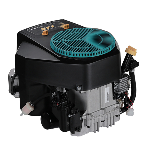
Part I Technical Specifications 1-1 Introduction of engine Air filter Fan cover comp. Cap assy Gasoline pump Valve-drain,oil Fuel filter Regulater voltage adjust carburetor assy Control assy Spark plug cap Secondary oil filters Starter motor - 1 -... -
Page 6: Technical Parameters
Part I Technical Specifications 1-2 Technical parameters Model 2P73F 2P76F Type OHV、V-twin Cylinders、Forced air cooling 、4-Stroke Max. power(kW/3600rpm) 14.17 /3600 14.92/3600 Net. Power (kW/rpm) 12.5/3600 13.5/3600 Max . torque (N·m/rpm/min) 37.0/(2400~2600) 40.0/(2400~2600) Idle speed 1850±150 rpm Bore X Stroke(mm) 73×70 76×70 Displacement(cc) Compression Ratio... -
Page 7: Model Installation Dimensional Drawing
Part I Technical Specifications 1-3 Model installation dimensional drawing - 3 -... -
Page 8: Dimensional Drawing
Part I Technical Specifications 1-4 P.T.O dimensional drawing Shaft A/Type A - 4 -... -
Page 9: Electric Wiring Diagram
Part I Technical Specifications 1-5 Electric wiring diagram - 5 -... -
Page 10: Part Ii Repair Instructions
2-1 Maintenance Precautions 5. Parts shall be cleaned after being dismantled and shall be coated with oil on the sliding surface 1. Use pure LONCIN parts or the specified parts and during assembly. lubricating oil. Parts not meeting LONCIN’s design specifications may damage the device or the engine. -
Page 11: Marking Position Of Machine No
P.: the page shall be referred to. 2-2 Marking position of machine No. Machine No. is marked on the crankcase as shown in the figure below. When LONCIN dealers require correct parts during maintenance, the machine number is used to check the engine or to order parts. -
Page 12: Maintenance Standards
Part II Repair Instructions 2-3 Maintenance standards Unspecified unit: mm Standard Service Limit Part Item LC2P73F LC2P73F Engine Ile speed (1800±150) rpm - Cylinder head Warpage 0.05 - Sleeve(inside diameter X) φ73.0~φ73.01 φ73.1 Cylinder Sleeve(inside diameter Y) φ73.0~φ73.01 φ73.1 Skirt outside diameter φ72.965~φ72.975... - Page 13 Part II Repair Instructions Standard Service Limit Part Item LC2P76F LC2P76F Engine Ile speed (1800±150) rpm - Cylinder head Warpage 0.05 - Sleeve(inside diameter X) φ76.0~φ76.01 φ76.1 Cylinder Sleeve(inside diameter Y) φ76.0~φ76.01 φ76.1 Skirt outside diameter φ75.965~φ75.975 φ75.755 Clearance to cylinder 0.025~0.045 0.255 Piston...
-
Page 14: Torque Parameters Of Fasteners
Part II Repair Instructions 2-4 Torque parameters of fasteners (1) Torque parameters of parts Torque Range Process Description Bolt Specification In.lb. Oil drain Connector Oil drain Connector 18~23 159.3~203.5 Spark Plug M14×1 25~30 221.2~265.3 Connecting Rod Cover Six Hexagonal Flange Bolt M6×35 11~13 97.4~115 Crankcase Cover Bolt... -
Page 15: Part Iii Maintenance
Part III Maintenance 3-1 Table of maintenance periods First 1 Every 3 Every 6 Every Every 2 Every Each Maintenance schedule month months or months or year or years or 300hou or 5 hours 25 hours 50 hours 100 hours 200 hours Oil level ●... -
Page 16: Change Engine Oil
Part III Maintenance 3-2 Change engine oil Note: drain engine oil when the machine is stopped but not cooled down so as to guarantee the fast and thorough exhaust of the oil. The engine oil of gasoline is the main factor that affects the Oil filler performance and life of gasoline. -
Page 17: Maintenance Of Air Filter
Part III Maintenance 3. Insert the oil filler cap/dipstick into the oil filler tube. Remove the oil filler cap/dipstick UPPER LIMIT and check the oil level on it. Bring the level to the upper mark on the dipstick. after running the engine, recheck the oil LOWER LIMIT The waste oil contains hazardous substances which may cause skin cancer for long-term exposure to the waste oil. -
Page 18: Maintenance Of Spark Plug
Part III Maintenance than 30 psi) through the filter from the inside. Never try to brush off the dirt. Brushing will force dirt into the filter fibers. 5. Use a damp rag to wipe any dirt from the inside of the air cleaner base and cover. Be careful not to allow dirt into the duct leading to the carburetor. -
Page 19: Adjustment Of Valve Clearance
Part III Maintenance the clearance is small). 5. Impact the gasket tightly with the socket spanner of spark plug. When re-installing a used spark plug, screw 1/8-1/4 circle more after the gasket is impacted. When installing new spark plug, screw 1/2 circle more after the gasket is impacted. Note Too loose spark plug may be overheat and damage the engine. -
Page 20: Adjustment Of Speed Regulator
Part III Maintenance Stop screw 1. Start the engine. And allow the engine to warm to normal operating temperature. 2. With the engine idling, adjust the throttle stop screw to obtain the recommended engine idle speed. Recommended idle speed: 1800±150 rpm Adjustment of speed regulator 1. -
Page 21: Storage Of Engine
Part III Maintenance 3-9 Storage of engine After it is shut down, cool the engine down for at least half an hour prior to cleaning. Clean the outer surface, repair the damaged baking finish and coat thin rust resisting oil on areas that are possible rust. Caution Washing water with high pressure can enter the air filter and silencer and even enter the cylinder along with the air passage and cause corrosion and damage. -
Page 22: Part Iv Faults Diagnosis
Part IV Faults Diagnosis 4-1 Difficulty of engine in starting Excessive engine oil (Stop for several minutes before restarting) Insufficient fuel (Add fuel oil into the fuel tank) Fuel system Fuel filter screen blocked (Clean fuel filter screen) Fault or improper adjustment of carburetor (Refer to Section 5-2-4) Air cleaner dirty (Clean or replace) -
Page 23: Underpower Of Engine
Part IV Faults Diagnosis 4-2 Underpower of engine Poor fuel quality (Use new fuel of designated quality) Fuel filter blocked (Clean fuel filter) Fuel system Fault or improper adjustment of carburetor (Refer to Section 5-2-4) Choke valve not fully opened (Open it to the maximum) Air filter dirty (Clean air filter) -
Page 24: Rotating Speed Instability Of Engine
Part IV Faults Diagnosis 4-3 Rotating speed instability of engine Fuel is insufficient/of poor quality/polluted (Use new fuel oil of specified quality) Fuel filter blocked Fuel system (Clean fuel filter) Carburetor blocked (Refer to Section 5-2-4) Spark plug blocked Rotational (Refer to Section 3-4) speed Ignition system... -
Page 25: Abnormal Exhaust Colors Of Engine
Part IV Faults Diagnosis 4-4 Abnormal exhaust colors of engine Air filter excessively dirty (Clean air filter) Fault of carburetor Black (Refer to Section 5-2-4) Overloaded (Alleviate load) Low temperature of engine Abnormal (Normal starting) exhaust color White Water contained in fuel (Use new fuel oil of specified quality) Engine oil contained in fuel (Use new fuel oil of specified quality) -
Page 26: Engine Is Easily To Be Flameout
Part IV Faults Diagnosis 4-5 Engine is easily to be flameout Spark plug dirty or wet (Refer to Section 3-5) Fuel level of carburetor too high Engine is (Adjust the height of the float of the carburetor) easily to be flameout Improper idle speed adjustment (Refer to Section 3-6) -
Page 27: Overheat Of Engine
Part IV Faults Diagnosis 4-7 Overheat of engine Wrong ignition time (Adjust ignition time) Engine oil insufficient or polluted (Add or replace engine oil) Silencer blocked Overheat Ring flutter of cylinder and crankcase due to of engine failure of piston ring causing (Replace worn parts) Too high rotational speed of gasoline engine (Repair speed-regulating system or replace speed-regulating gear) -
Page 28: Abnormal Noises Of Engine
Part IV Faults Diagnosis 4-8 Abnormal noises of engine Wear of piston and piston ring (Replace piston and piston ring) Wear of connecting-rod, piston pin and pin hole (Replace worn parts) Rattle Wear of crankshaft bearing (Replace wore parts) Breakage of piston ring (Replace piston ring) Excessive carbon deposition in combustor (Remove carbon deposition) -
Page 29: Fault Of Electric Starting System
Part IV Faults Diagnosis 4-9 Fault of electric starting system Battery fault (Charge or replace) Short circuit or broken circuit of lead wire or connecting plug No click sound (Repair or replace) Fuse burn-out (Replace) Dose electric relay Fault of engine switch (switch) have (Repair or replace) -
Page 30: Check The Cylinder Pressure
Part IV Faults Diagnosis 4-10 Check the cylinder pressure 1) Disassemble spark plug cap and spark plug. 2) Assemble pressure meter in the spark plug hole. 3) Use starter motor make the engine runing. Cylinder Right = 10 ~13 bar pressure Left = 3 bar NOTE... -
Page 31: Part V Disassembly & Repair
Chapter V Disassembly & Repair 5-1 Precautions on disassembly/assembly 5-1-1 Disassembly 1. Get familiar with the constitution and operating principle of the machine prior to disassembly, which is the precondition for correct disassembly. 2. Not disassemble those without the need. Blind disassembly will not only increase workload of repair but also damage the original good coordinating relation and precision among parts so as to cause new hidden faults. -
Page 32: Disassembly And Maintenance Of Engine
Chapter V Disassembly & Repair 5-2 Disassembly and maintenance of engine 5-2-1 Air filter Handle,air Air filter cover cleaner bolt Element assy Assembly Clean or replace dirty damaged filter cartridges. Flange nut M6 Torque: (8 ~12) N•m Air filter seat Disassembly/assembly: clean the inside with compressed air and then install. -
Page 33: Fan Cover
Chapter V Disassembly & Repair 5-2-2 Fan cover Air filter cover Starter shroud Cover comp.,fan Bolt,hexagonal Bolt,flange M6 ×65 Torque: (8 ~ 12) N•m Cover fan Fan,cooling Assembly: Align cams at the inner side with the small holes on the flywheel. Avoid excessive force... -
Page 34: Control Level
Chapter V Disassembly & Repair 5-2-3 Control level Throttle return spring Assembly: Replace deformed or damaged spring. Reset spring Rod,choke Rod,Throttle governor Throttle, Speed-regulating support Spring,governor Assembly: Adjust the speed regulator Assembly: during assembly. Replace deformed damaged spring. - 30 -... -
Page 35: Carburetor
Chapter V Disassembly & Repair 5-2-4 Carburetor Warning The gasoline is flammable and explosive. The fuel stop valve must be closed before repairing the carburetor and drain the fuel in the carburetor. Seal Assembly Deformation rupture should Fuel tube replaced in time It shall be regularly replaced every two years. - Page 36 Chapter V Disassembly & Repair Disassembly/assembly Note: clean the carburetor prior to installation Idle jet Assembly: Clean thoroughly with compressed air Idle mixture adjusting screw before installation and slightly lubricate the O-ring. O-ring Assembly: Check the wear at the front before installation.
- Page 37 Chapter V Disassembly & Repair Clean the carburetor Warning When using the compression air, to avoid injury, wear protective spectacles or other protective equipment. Note Some chemical solvents are of relatively-strong corrosivity and may damage plastic parts such as the O-ring and float. Please carefully read the Solvents Manual.
-
Page 38: Flywheel And Ignition Coil
Chapter V Disassembly & Repair 5-2-5 Flywheel and ignition coil Flywheel a. Disassembly/assembly Disassembly: Disassemble the ignition coil prior to the disassembly of flywheel; Do not tap the flywheel with hammer and disassemble it with a commercially Flywheel bolt M12 × 35 available flywheel puller. - Page 39 Chapter V Disassembly & Repair b.Adjustment of clearance between ignition coils When reassembling igniting coil, adjust the igniting coil gap. 1) Lightly tighten the igniting coil mounting bolt. 2) Insert the feeler gauge or a piece of paper of the same thickness between the flywheel and coil as shown.
- Page 40 Chapter V Disassembly & Repair Charging System Charging System Operational Inspection 1. Check battery condition. 2. Always check battery condition before condemning other parts of the charging system. The battery must be fuly charged in order to conduct accurate charging system tests. 3.
- Page 41 Chapter V Disassembly & Repair 3000r/min, Load with 8Ω, I≥8.0A; 0.23 Ω Charging coil resistance: ±10% 2. In the case of detecting the output of the charging coil, check the voltage of the battery (generally in 12v~ 12.4V), start the engine, the multimeter is placed in the dc file, and then the voltage of the battery, If the voltage is less than 13V.please replace the pressure rectifier.
-
Page 42: Cylinder Head And Valve
Chapter V Disassembly & Repair 5-2-6 Cylinder head and valve Disassembly/assembly Flange bolt M10 × 70 Torque: (50 ~ 55) N•m Assembly/disassembly: Flange bolt M6 × 25 Loosening and fastening of bolt must be done by Cylinder-head Torque: (8 ~ 12) N•m cover sealing way of crossing, especially when fastening the bolt. - Page 43 Chapter V Disassembly & Repair Valve rocker arm Assembly: Pivot lock nut Check if the contact surface of rocker arm, central hole or Tappet combination Torque: ( 12 ~ 16) N•m valve lifter is worn prior to Assembly: installation. Confirm the wear of two ends and upright of lifter body, and then pass through the guide hole and place into Pivot bolt...
- Page 44 Chapter V Disassembly & Repair Free length of the valve spring Measure the free length of valve spring. Standard Maintenance Limit 39.5mm~40.5 mm 39mm Replace the spring if the maintenance limit is exceeded. Width of valve seat Remove the carbon deposition in combustor and check if the valve seat has corrosion or damage.
- Page 45 Chapter V Disassembly & Repair Standard Maintenance Limit Inlet valve 6.565-6.58 mm 6.515 mm Exhaust valve 6.545-6.56 mm 6.495 mm Replace the valve if the outer diameter of valve stem is less than the maintenance limit. Inner diameter of valve guide Remove the carbon deposition in the exhaust valve pipe with reamer prior to measurement.
- Page 46 Chapter V Disassembly & Repair seat. 4. Grind the valve seat with a 45° grinder to make the valve seat smooth and concentric; operate as per the manual of valve seat grinder provided by the manufacturer. Rotate the grinder clockwise and the anticlockwise rotation is not allowed. Lift the valve seat grinder from the valve seat and continue grinding.
-
Page 47: Speed-Regulating Arm, Breather Slot
Chapter V Disassembly & Repair 5-2-7 Speed-regulating arm, breather slot Disassembly/assembly Oil seal 35 × 52 × 7 mm Tube, breather Assembly: don’t curl the edge of oil seal when Assembly passing through Deformation crankshaft. rupture should be replaced in time Breather-slot cover plate Breather-slot Filter screen... -
Page 48: Crankcase Cover And Governor
Chapter V Disassembly & Repair 5-2-8 Crankcase cover and governor Disassembly / reassembly NOTICE: Check that the governor move smoothly. Speed gear pressing, axial clearance should be guaranteed to 0.05~0.35mm. - 44 -... - Page 49 Chapter V Disassembly & Repair Seal ring Assembly Deformation rupture should be replaced in time Cap assy Engine-oil filter screen Dirty or damaged one shall cleaned replaced immediately. Secondary oil filters Torque: ( 9~ 13) N.m Governor gear Confirm if there is engine oil leakage after installation.
- Page 50 Chapter V Disassembly & Repair Check Installation check of oil pump 1、 Rotational flexibility of rotator: coat lubricating oil onto rotator and axis prior to assembly; manually rotate the rotational Inner rotor axis after assembly to assure no binding in rotation process. Sealing ring 2、...
-
Page 51: Crankcase, Crankshaft And Piston
Chapter V Disassembly & Repair 5-2-9 Crankcase, crankshaft and piston Disassembly/assembly Crankcase Camshaft Align the gear of camshaft with the timing gear on the crankshaft during installation. Comparison mark Connecting-rod bolt Torque:11~13 N.m Connecting rod Crankshaft part Assembly: coat adequate Assembly: lubricating oil on the bigger Piston... - Page 52 Chapter V Disassembly & Repair Triangle mark on the piston should point crankcase cover The installation of connecting rod, connecting rod big end hole of the installation of two large chamfer in the opposite direction. - 48 -...
- Page 53 Chapter V Disassembly & Repair Disassembly/assembly Piston and connecting rod Assembly: . Put upward the manufacturer’s mark during assembly. Ring 2 . Do not misplace the gas rings 1 and 2. Opening of ring 2 Piston mark . Check if the piston ring can rotate Ring 1 flexibly after installation.
- Page 54 Y axis is parallel to crankshaft). Take the maximum reading as the wear and conical degree of the cylinder. Model Standard Maintenance Limit LC2P73F 73~73.01 mm 73.1 mm LC2P76F 76.0~76.01 mm 76.1 mm Detection of piston and piston ring Check the contact between piston and cylinder, defects of ring groove, erosion at the top, crack, etc.
- Page 55 Chapter V Disassembly & Repair Clearance between piston and cylinder The difference between the maximum diameter of cylinder and the diameter of the piston skirt is the clearance between piston and cylinder. Standard Maintenance Limit 0.025 ~ 0.045 mm 0.255 mm Clearance to the side of piston ring Standard Maintenance Limit...
- Page 56 Chapter V Disassembly & Repair Detection of connecting rod The connecting rod shall be scrapped to change a new one when it is bent or warped, or there is abnormal wear to the larger end and small end hole or there is crack of one side. Inner diameter of the small end of connecting rod Change the connecting rod if the inner diameter is less than the standard or more than the maintenance limit.
- Page 57 Chapter V Disassembly & Repair Oil-film clearance of big end of connecting rod (radial direction) 1) Clean the surface of crankshaft journal and the inside oil. 2) Set plastigauge on crank journal then assemble the connecting 12 N.m±1 N.m rod, and fasten the bolt as per the specified torque. Fastening torque: 12 N.m±1 N.m Note Don’t rotate the crankshaft when fastening the connecting-rod bolt.
- Page 58 Chapter V Disassembly & Repair Outer diameter of camshaft Standard Maintenance Limit 15.966~15.984mm 15.916mm Note the position of depression mechanism and check to ensure its flexibly. Inner diameter of camshaft bearing hole Standard Maintenance Limit 16.0-16.018 mm 16.068 mm - 54 -...
- Page 59 LONCIN MOTOR CO., Ltd. Add: No.99 Hualong Road, Jiulongpo District, Chongqing, China Tel: 86 23 8906 7577/7599 Fax: 86 23 8906 7533 Web site: www.loncinengine.com E-Mail: marketing@loncinengine.com - 55 -...
Need help?
Do you have a question about the LC2P73F and is the answer not in the manual?
Questions and answers
is silencer part no. 180571314-0001 correct for this motor