Advertisement
Quick Links
Service
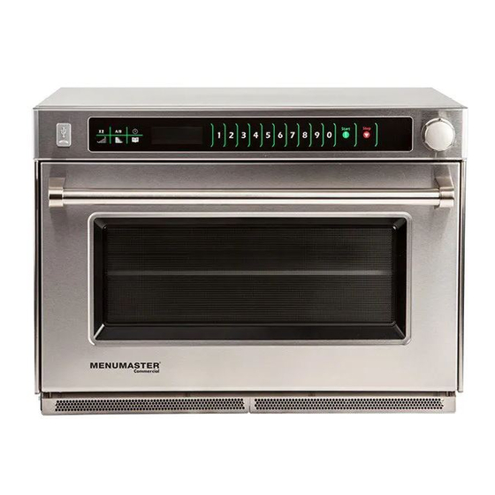
Commercial Microwave Oven
AMSO & MSO Models
Service Manual
This manual is to be used by qualified
service technicians only. ACP, Inc.
does not assume any responsibility for
property damage or personal injury for
improper service procedures done by
an unqualified person.
This Base Manual covers all
Commercial Microwave Ovens.
Refer to individual Technical Sheet
for information on specific models.
MSO35OS
AMSO5353
December 2015
MSO22
MSO35
MSO5211
MSO5351
MSO5353
AMSO22
AMSO35
16400029
Revision 1
Advertisement

Related Manuals for ACP MSO22


Summary of Contents for ACP MSO22
- Page 1 AMSO & MSO Models AMSO35 AMSO5353 Service Manual This manual is to be used by qualified service technicians only. ACP, Inc. does not assume any responsibility for property damage or personal injury for improper service procedures done by an unqualified person.
- Page 2 16400029 Revision 1 December 2015...
- Page 3 TABLE OF CONTENTS IMPORTANT SAFETY INSTRUCTIONS ................1-3 Oven Specifications ......................4 Installation & Cleaning ......................5 Quick Start Reference Guide ..................... 6-7 User Options ......................... 8 Cooking Instructions ......................9 Component Location ...................... 10-15 Door and Door Switch Adjustment ................. 16-18 Service Test Mode ......................
- Page 4 –Outside the U.S.A. and Canada, call 319-368-8120. –Email: Commercialservice@acpsolutions.com. Warranty service must be performed by an authorized ACP servicer. ACP also recommends contacting an authorized ACP servicer, or ACP ComServ Service Support if service is required after warranty expires. PRECAUTIONS TO AVOID POSSIBLE EXPOSURE...
- Page 5 To reduce the risk of burns, electrical shock, fire, or personal injury when using ARNING electrical equipment, basic safety precautions should be followed. READ AND FOLLOW the specific DO NOT use the cavity for storage. DO NOT leave paper products, cooking utensils, or food in the cavity when not in “PRECAUTIONS TO AVOID POSSIBLE use.
- Page 6 To avoid risk of personal injury or property damage, observe the following safety CAUTION instructions: General Use: 11. Do not heat sealed containers or plastic bags in 1. Do not use regular cooking thermometers oven. Food or liquid could expand quickly and in oven.
- Page 7 To avoid risk of electrical shock, personal injury, or death, disconnect power to oven and discharge capacitor before servicing, unless testing requires power. Models AMSO22 AMSO35 MSO5211 MSO5351 AMSO5353 MSO22 MSO35 MSO5353 MSO35OS Power Source Voltage AC 240/208 VAC 240/208 VAC...
- Page 8 Cleaning Interior, Exterior, and Door specifications (available on ACP’s Clean microwave oven daily with mild detergent in warm water website at www.acpsolutions.com). using soft sponge or cloth. Wring sponge or cloth to remove When a microwave oven is on a circuit excess water before wiping equipment.
- Page 9 QUICK START REFERENCE GUIDE 16400029 Revision 1 December 2015...
- Page 10 16400029 Revision 1 December 2015...
- Page 11 USER OPTIONS 16400029 Revision 1 December 2015...
- Page 12 COOKING INSTRUCTIONS 16400029 Revision 1 December 2015...
- Page 13 COMPONENT LOCATIONS 16400029 Revision 1 December 2015...
- Page 14 16400029 Revision 1 December 2015...
- Page 15 16400029 Revision 1 December 2015...
- Page 16 16400029 Revision 1 December 2015...
- Page 17 16400029 Revision 1 December 2015...
- Page 18 16400029 Revision 1 December 2015...
- Page 19 DOOR & DOOR SWITCH ADJUSTMENT 1. Remove the outer case. 2. Using a pencil or pen, mark the position of both door hinge arms as shown in Figure 1. Figure 1 3. While holding the door closed, carefully remove both door springs and open the door the full position. 4.
- Page 20 5. Remove the Door Hinge Screws (2 on each side) and remove the old door. 6. Place the new door into position and install the new TC/Hex Screws finger tight. 7. Place a small drop of the provided Blue Threadlock to the threads of the new Shoulder Bolts and reattach Door Arms, Hole Plugs, and Door Springs.
- Page 21 8. Using the 2mm Hex Key Wrench as a spacer between the top of the Door and the Control Panel, pull down on the Door Handle and observe the hinge arm. When the Hinge Arm aligns with the mark made in Step 2, tighten the Door Hinge TC/Hex Screws securely and repeat on the other side.
- Page 22 SERVICE TEST MODE HIDDEN PAD MSO Units have an easily accessed Service Mode that allows a technician to operate components, clear service alarms, check door cycles, and check magnetron hours. To enter the Service Mode, perform the following: PRESS and RELEASE the Hidden Pad PRESS and RELEASE In Order: 1, 3, 5, 7, 9.
- Page 23 MICROWAVE POWER TEST Power Test All ACP microwave oven power outputs are rated using the IEC705 standards. Using the IEC705 test method requires precision measurements and equipment that is not practical to be performed in the field. Using the test shown below will indicate if the oven performance is satisfactory.
- Page 24 COMPONENT SPECIFICATIONS Illustration Component Testing Results Disconnect all wires from motor Measure resistance across terminals……... 12.2K Ω Antenna Motor Remove fuse and check end-to-end 12 amp (qty 4)………………………………. Continuity Fuses 30 amp (qty 2)………………………………. Continuity HV Transformer Secondary 800ma (qty 4).. Continuity IF MAIN FUSE IS OPEN, THE FUSE AND MONITOR RELAY BOARD MUST BE...
- Page 25 NOTE: Analog meter must contain a Reverse leads for second test. battery of 6 volts minimum. Discharge Capacitors ! MSO22 .55µ (bottom) .65µ (top) Between Terminals: Meter should momentarily deflect towards zero MSO35 .90µ then return to over 5 MΩ. If no...
- Page 26 Disconnect wires to switch. With door open measure resistance from: Terminal to Terminal ……………………… Open/Infinite Interlock Switch Assembly Upper - RIGHT With door closed measure resistance from: Terminal to Terminal…………………….. Closed/Continuity Disconnect wires to switch. With door open measure resistance from: Terminal to Terminal ………………………...
- Page 27 Line to Line…………………………………… .8MΩ Load to Load…………………………………. Line Filter .8MΩ Line to Load………………………………….. Closed/Continuity Any Terminal to Earth……………………….. Open/Infinite Error Code Table The oven has built-in diagnostics. Below is a table of Errors and their causes: Error Code Corrective Action Replace HV/LV Board Replace HV/LV Board Replace HV/LV Board...
- Page 28 SCHEMATICS & DIAGRAMS MSO22 AMSO22 16400029 MSO35* AMSO35 Revision 1 December 2015...
- Page 29 SCHEMATICS & DIAGRAMS MSO5211 MSO5351 16400029 Revision 1 December 2015...
- Page 30 SCHEMATICS & DIAGRAMS MSO22 AMSO22 MSO5211 MSO35* AMSO35 MSO5351 16400029 Revision 1 December 2015...
- Page 31 SCHEMATICS & DIAGRAMS MSO5353 AMSO5353 16400029 Revision 1 December 2015...
- Page 32 SCHEMATICS & DIAGRAMS MSO5353 AMSO5353 16400029 Revision 1 December 2015...
Need help?
Do you have a question about the MSO22 and is the answer not in the manual?
Questions and answers