Advertisement
Quick Links
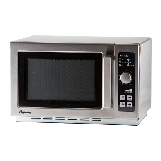
Commercial Microwave-Technical Information
120 VAC, 60 Hz model
RCS10DSE
MCS10DSE
• Due to possibility of personal injury or property damage, always contact an authorized technician for servicing or
repair of this unit.
• Refer to Service Manual for installation, operating, testing, troubleshooting, and disassembly instruction.
All safety information must be followed as provided in Service Manual.
To avoid the risk of electrical shock, personal injury or death; disconnect power to oven and discharge capacitor
before servicing, unless testing requires power.
Power Source
Voltage AC
Amperage (Single Unit)
Frequency
Single Phase, 3 wire grounded
Receptacle
Plug
Power Output − − − − Microwave
Nominal microwave energy (IEC705)
Minimum temperature rise (ΔT)
Operating Frequency
Power Consumption
Microwave only
Dimensions
Cabinet (in cm)
Width
Height
Depth
Oven Interior (in cm)
Width
Height
Depth
Weight
Uncrated
Features
Timer
Cavity Volume
August 2012
©2012 ACP Inc.
P2001102M
P2001104M
!
CAUTION
!
WARNING
Models
1
RCS10DSE / MCS10DSE
120 VAC
15 A
60 Hz
X
5-15R
5-15P
1000 Watts
10ºF / 5ºC
2450 MHz
1550 Watts
22"
56 cm
13 3/4"
34.9 cm
19"
48.2 cm
14 1/2"
36.8 cm
8 1/2"
21.6 cm
15 "
38.1 cm
41 lbs.
18.6 kg
10 minute single speed
1.2 cu. Ft.
16500040
Advertisement

Subscribe to Our Youtube Channel
Related Manuals for ACP RCS10DSE


Summary of Contents for ACP RCS10DSE
- Page 1 All safety information must be followed as provided in Service Manual. WARNING To avoid the risk of electrical shock, personal injury or death; disconnect power to oven and discharge capacitor before servicing, unless testing requires power. Models RCS10DSE / MCS10DSE Power Source Voltage AC 120 VAC Amperage (Single Unit)
-
Page 2: Component Testing Procedures
Primary Ω Secondary to Ground screw on transformer stack ......... Approximately 75 Ω Lamp and receptacle Test continuity of receptacle terminals. Indicates continuity with bulb installed. Wire Harness Test continuity of wires Indicates continuity 16500040 August 2012 ©2012 ACP Inc. - Page 3 120 VAC OFF position (Door Closed) 0 volts Cook mode (Door Closed) (Relay 2) Measure voltage across BL and WH terminal leads ....120 VAC OFF position (Fan/Light Relay 2 Off) Relay 1 0 volts (Fan/Light ON) August 2012 16500040 ©2012 ACP Inc.
-
Page 4: Power Test
17 ....1700 25 ....2500 9.5 .... 1700 13.5 ..2500 18 ....1800 27 ....2700 10 ..... 1800 15 .... 2700 19 ....1900 30 ....3000 10.5 ..1900 16.5 ..3000 16500040 August 2012 ©2012 ACP Inc. -
Page 5: Wiring Diagram And Schematic
Wiring Diagram and Schematic WARNING To avoid risk of electrical shock, personal injury or death; disconnect power to oven and discharge capacitor before servicing, unless testing requires power. August 2012 16500040 ©2012 ACP Inc.
Need help?
Do you have a question about the RCS10DSE and is the answer not in the manual?
Questions and answers