Advertisement
Quick Links
Support and E-Warranty Certificate https://www.vevor.com/support
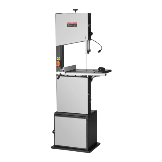
BAND SAWR
USR MANUAL
MODEL:HBS350
We continue to be committed to provide you tools with competitive price.
"Save Half", "Half Price" or any other similar expressions used by us only represents an
estimate of savings you might benefit from buying certain tools with us compared to the major
top brands and doses not necessarily mean to cover all categories of tools offered by us. You
are kindly reminded to verify carefully when you are placing an order with us if you are
actually saving half in comparison with the top major brands.
Advertisement

Related Manuals for VEVOR HBS350


Summary of Contents for VEVOR HBS350
- Page 1 Support and E-Warranty Certificate https://www.vevor.com/support BAND SAWR USR MANUAL MODEL:HBS350 We continue to be committed to provide you tools with competitive price. "Save Half", "Half Price" or any other similar expressions used by us only represents an estimate of savings you might benefit from buying certain tools with us compared to the major top brands and doses not necessarily mean to cover all categories of tools offered by us.
- Page 2 CustomerService@vevor.com This is the original instruction, please read all manual instructions carefully before operating. VEVOR reserves a clear interpretation of our user manual. The appearance of the product shall be subject to the product you received. Please forgive us that we won't inform you again if there are any technology or software updates on our product.
- Page 3 READ THESE INSTRUCTION CAREFULLY BEFORE COMMISSIONING AND OPERATING THIS BAND SAW COMPONENTS AND PARTS (STANDARD DELIVERY ) Front 11. Lower Housing Door 1. Upper Housing Door 12. Rip Fence 2. Setting Knob for Band Saw Blade Tension 13.On/Off Switch With 3.
- Page 4 Back 14. Quick Release Lever for Band Saw Blade 15.Setting Knob for Blade Tracking Adjustment 16.Setting Knob for Table Turning Adjustment 17.Motor 18.Machine Base 19.Dust Extraction Port 20.Setting Knob for Drive Belt 21.Mitre 22.Table Insert 23.Stand Cabinet 24.Push Stick TABLE OF CONTENTS Components And Parts(Standard Delivery)..........2 Please Read First!..................4 Safety ......................6...
- Page 5 PLEASE READ FIRST! These operating instructions have been written to make it easier for you, the user, to learn how to operate this machine and to do so safely. These instructions should be used as follows: Read these instructions before use. Pay special attention to the safety ...
- Page 6 Caution! Risk of material damage. Note:Additional information. Warning- Be sure to wear ear protectors when using this product. Warning- Be sure to wear eye protectors when using this product. Warning- Be sure to wear gloves when using this product. This product is of protection class II. That means it is equipped with enhanced or double insulation.
- Page 7 SAFETY WARNING:Read all safety warnings,instructions,illustrations and specifications provided with this band saw.Failure to follow all instructions listed below may result in electric shock, fire and/or serious injury. Save all warnings and instructions for future reference. General Power Tool Safety Warnings-Work Area Safety a)Keep work area clean and well-lit.
- Page 8 shock. e)When operating a power tool outdoors, use an extension cord suitable for outdoor use. Use of a cord suitable for outdoor use reduces the risk of electric shock. f)If operating a power tool in a damp location is unavoidable,use a residual current device(RCD)protected supply.Use of an RCD reduces the risk of electric shock.
- Page 9 h)Do not let familiarity gained from frequent use of tools allow you to become complacent and ignore tool safety principles.A careless action can cause severe injury within a fraction of a second. Power Tool Use and Care a)Do not force the power tool. Use the correct power tool for your application.
- Page 10 identical replacement parts.This will ensure that the safety of the power tool is maintained. 1. Specified Conditions of Use The machine is suitable for cutting wood,wood-derived materials and plastics.Do not cut round stock transverse to its longitudinal axis without suitable jigs or fixtures.The rotating saw blade could turn the workpiece.When sawing thin stock lay on edge,a suitable guide must be used for firm support.
- Page 11 Do not permit other persons to touch the tool or power cable while it is running. Do not overload tool ¨C use it only within the performance range it was designed for(see"Technical specifications"). Danger!Risk of Electric Shock! Do not expose tool to rain.Do not operate tool in damp or wet environment.Prevent body contact with earthed objects such as radiators,pipes,cooking stoves,refrigerators when operating this tool.
- Page 12 sharp band saw blades. If in doubt,check workpiece for inclusion of foreign matter(e.g.nails or screws). Cut only stock of dimensions that allow for safe and secure holding while cutting.Never cut several workpieces at the same time and also no bundles containing several individual pieces.Risk of personal injury if individual pieces are caught by the band saw blade uncontrolled.
- Page 13 Dust of certain timber species(e.g.oak,beech,ash)can cause cancer when inhaled:work only with a suitable dust collector connected to the saw. Hazard generated by modification of the machine,or use of parts not tested and approved by the equipment manufacturer! Assemble tool in strict accordance with these instructions.Use only parts approved by the equipment manufacturer.Use only tools(band saw blades)conforming to EN 847-1:1997.
- Page 14 Band saw blade running direction. 4. Safety Devices Upper Blade Guard The upper blade guard(26)protects against unintentional contact with the saw blade and from chips flying about.In order for the upper blade guard to - 13 -...
- Page 15 provide adequate protection against contact with the band saw blade,it must always be set as close as possible to the workpiece (max.distance 3 mm). Lower Blade Guard The lower blade guard(27)protects against unintentional contact with the saw blade. The lower blade guard must always be in place and cover the band saw blade while the band saw is running.
- Page 16 MACHINE DETAILS Note:In this chapter, the essential operating elements of the machine are introduced. The proper use of the machine is described in chapter"Operation".Read this chapter before using the saw for the first time. ON/OFF Switch with Emergency Stop To start=press the green switch button(29). ...
- Page 17 With the setting knob(31)the band saw blade tension is corrected,if necessary: -Turning the setting knob clockwise increases the blade tension. -Turning the setting knob counterclockwise reduces the blade tension. Quick Release Lever With the quick release lever(32)the saw blade tension is released. - 16 -...
- Page 18 Setting Knob for Blade Tracking Adjustment With the setting knob(33)the tilt of the upper band saw wheel can be adjusted,if necessary.This tracking adjustment is required to have the blade run dead center on the rubber tyres of the band saw wheels: -Turning clockwise=blade moves to the rear.
- Page 19 Speed Adjustment Adjust the hand wheel to adjust the speed of the band saw: low speed for hard wood,plastics. high speed for all kinds of wood. With the setting knob(34)the drive belt tension is corrected,if necessary Turning the setting knob clockwise reduces the blade tension. ...
- Page 20 Rip Fence The rip fence(37)clamps to the front of the bandsaw table;The rip fence can be used on both sides of the blade. Mitre Fence The mitre fence is inserted into the table slot from the table’s front edge.For mitre cuts the mitre fence turns to60°in both directions For 45°and 90°miters positive stops are provided.To set a mitre angle:loosen lock handle(38)by turning it counter-clockwise.
- Page 21 -Safety devices have been checked.Connect the saw to the mains supply only after all of the above preparations are completed! Otherwise there is a risk of an unintentional starting of the saw,which can cause severe personal injury. 1. Mounting For a firm stand the saw must be mounted on a stable supporting surface: 1).Drill 4 holes in the supporting surface.
- Page 22 3).Attach the saw table with four each screws(39)and washers to the table trunnion. 3. Aligning the Saw Table The saw table needs to be aligned in two planes -Laterally,in order for the blade to run dead centre through the table insert;...
- Page 23 3).Tighten the four fastening screws(35)again. Aligning the Working Table at Right Angles to the Band Saw Blade 1).Raise upper blade guide fully(see"Operation").Check band saw blade tension(see"Initial operation"). 2).Loosen the lock lever. 3).Using a try square,set the table at right angles to the blade and tighten the lock lever again.
- Page 24 5).Tighten the locking nut. 4. Installing the Fence Guide Extrusion Fasten the fence guide extrusion(58)with four thumb screws and washers to the saw table. 5. Installing the Rip Fence The rip fence can be used on both sides of the blade.When the rip fence is moved from one side of the saw blade to the other the fence extrusion(44)needs to be reversed.
- Page 25 holder can only be installed afterward. 1) Turn a hexagon nut on a cap screw(46),all the way up to the unthreaded part of the shank. 2) Turn cap screw into the hole on the left side of the band saw. 3) Tighten hexagon nut hand-tight only.
- Page 26 the correct adjustment in dependence on the band saw blade width. 3. Correct tension if necessary:turning the setting knob(48) counter-clockwise increases the blade tension.T urning the setting knob(48)counter-clockwise reduces the blade tension. 9. Connection to Power Mains Danger!High Voltage Operate the saw only in a dry environment.
- Page 27 section(3 x 1.5 mm2,for machines with 3-phase motor:5 x 1.5 mm2). Do not pull on the power supply cable to unplug. 1. When the saw is assembled and all safety devices are installed,connect it to the power supply. 2. Start saw briefly and turn OFF immediately again. 3.
- Page 28 Use personal protection gear: Dust respirator; Hearing protection; Safety goggles. Cut only one workpiece at a time. Always hold the workpiece down on the table. Do not jam the workpiece. Do not attempt to stop the band saw blade by pushing the workpiece against its side.
- Page 29 Assume correct work position(the band saw blade's teeth must point towards the operator). Never cut several workpieces at the same time, and also, any bundles containing several individual pieces. Risk of personal injury if individual pieces are caught by the saw blade uncontrolled Drawing-in/trapping hazard! Do not wear loose clothing,jewellery,or gloves,which may get caught ...
- Page 30 tilt: Switch machine OFF. Wait until the band saw blade has come to a complete stop.Set upper blade guide(50)with the adjusting knob(49)to the desired Cutting Speed Adjustment 1. Adjust the hand wheel to adjust the speed of the band saw. 2.
- Page 31 Note:Always make a trial cut in a piece of scrap to verify settings;correct if necessary before cutting the workpiece. 6) Place workpiece on the saw table. 7) Plug in. 8) Start saw. 9) Cut workpiece in a single pass. 10) Switch off if no further cutting is to be done immediately afterwards. CARE AND MAINTENANCE Danger!Prior to all servicing: Switch machine OFF.
- Page 32 2. Open both housing doors. 3. Set the upper blade guide(55)to its lowest position. 4. Loosen quick release lever(53)until the band saw blade has slackened. 5. To remove the band saw blade,guide it through The slot in the saw table ...
- Page 33 The blade cover on the saw housing(54)and The blade guides. 6. Fit a fresh band saw blade.Observe correct position:the teeth point towards the front(door)side of the saw. 7. Center band saw blade on the rubber tyres of the band saw wheels. 8.
- Page 34 -Turn setting knob(57)clockwise if the band saw blade runs towards the front of the saw. -Turn setting knob(57)counterclockwise if the band saw blade runs towards the rear of the saw. 3. Tighten lock nut(56). 3. Aligning the Upper Blade Guide The upper blade guide consists of: A thrust bearing(supporting the band saw blade from the rear) ...
- Page 35 2.Loosen fixing screw of the upper blade guide. 3.Align upper blade guide 4.Tighten the upper blade guide's fixing screw. 5.Loosen the thrust bearing's lock screw. 6.Adjust thrust bearing position(distance thrust bearing-band saw blade=0.5 mm–if the band saw blade is turned by hand,it must not touch the thrust bearing).
- Page 36 6. Replacing the Table Insert The table insert needs replacement when its slot has become enlarged or damaged. 1. Remove table insert(61)from saw table(push up from underneath). 2. Fit new table insert. 7. Cleaning the Saw 1.Open the housing doors. 2.Remove chips and sawdust with brush or vacuum cleaner.
- Page 37 8. Storage Danger!Store saw where It cannot be used or tampered with by unauthorized persons and Nobody can get hurt by the machine. Note: The ON/OFF switch can be safeguarded by a padlock. Caution! Do not store the saw outdoors,in unprotected areas or in damp or wet locations.
- Page 38 3.Loosen the spring with a spring clamp. 4.Take off the lower wheel and replace the belt - 37 -...
- Page 39 REPAIRS Danger! Repairs to electric tools must be carried out by qualified electricians only! Electric tools in need of repair can be sent to the service center of your country.Refer to the spare parts list for the address. Please attach a description of the fault to the electric tool. ENVIRONMENTAL PROTECTION All packaging materials are 100%recyclable.Worn out power tools and accessories contain considerable amounts of valuable raw and rubber...
- Page 40 Motor overheated,e.g.by a blunt band saw blade or chip build-up in the housing: Remove cause for overheating,let cool down for a few minutes,then start again. Band saw blade wanders off the line of cut or runs off the band saw wheels Band saw blade is not running dead center on the band saw wheels: Correct tracking(see"Care and maintenance").
- Page 41 TECHNICAL SPECIFICATIONS 1100W POWER Max. Throat width 340mm Max.cutting height 330mm Sawblade lenght 2780mm Sawtable size: 400*548mm Max.Sawblade speeds(50Hz) 880m/min Max.Sawblade speeds(60Hz) 1050m/min 83KG 112KG ELECTRICAL WIRING DIAGRAM - 40 -...
- Page 42 EXPLODED VIEW DRAWING AND PART LIST Band Saw Cabinet Stand - 41 -...
- Page 43 Item Drawing No. Name Q’TY DJ350A01012 Left End Panel GB/T17880.1 M6X13.5 DJ350A01014 Front Bracing Member GB97.1-85 6 Washer GB5783-86 M6×16 Hex Bolt DJ350A01013 Back Panel DJ350A01011 Right End Panel DJ350A03002 Turn-Lock Fastener GB70-85 M6×16 Bolt DJ350A01015 Base GB6170-86 M6 Hex Nut GB889-86 M6 Hex.
- Page 44 - 43 -...
- Page 45 ITEM PART NO. NAME Q'ty DJ350A04100 Lower Door GB70-85 M6×16 Hex. Socket Set Columned Head Bolt DJ350A04004 Spacer Bushing GB889-86 M6 Locking Nut GB6170-86 M4 DJ350A03102 Joining Block 31503035 Spring Plate GB12618-90 4×10 Rivet GB818-85 M4×16 Cross Recessed Pan Head Screw DJ350A03100 Upper Door GB894.1-86 15...
- Page 46 31503014B Guide Carrier System GB845-85 ST4.8×22 Cross Recessed Pan Head Tapping Screw DJ315S03012A-1 Adjusting Nut DJ315S03012A-2 Guiding Shaft GB77-85 M8×30 Hex. Socket Set Columned Head Bolt GB77-85 M6×6 Hex. Socket Set Screw GB/T278-89 80027 Bearing DJ315S03012A Three Roller Guide Housing DJ315S03012A-3 Shaft For Pilot DJ35003025A...
- Page 47 DJ38003007 Quick Release Shaft GB6172-86 M10 Hex. Thin Nut TJ315B03002-1 Locking Handle GB6170-86 M10 Hex. Nut 31503008-2 Setting Knob 31503008-1 GB5783-86 M8x45 Hex. Bolt GB5783-86 M8x 16 Hex. Bolt GB97.1-85 8 Washer 31503007 Wing Nut GB5783-86 M6X10 Hex. Bolt GB97.1-85 6 Washer DJ350A03002 Locking Door Knob...
- Page 48 DJ350A02002 Table Trunnion DJ350A02100 Table Trunnion Lower DJ350A02006 Pointer GB818-85 M4×6 Cross Recessed Pan Head Screw GB5783-86 M6X6 Hex. Bolt DJ315S02014 Cup Head Square Neck Bolt DJ350A02001 Table DJ350A02004 Table Insert DJ315S02001-16 Wing Nut DJ315S02001-18 DJ315S02001-09 Fence Bracket GB/T801-98 M6×45 Cup Head Square Neck Bolt DJ315S02001-10 Fence...
- Page 49 31504019 Setting Collar DJ350A04006 Shaft For Belt Tension GB818-85 M4×35 Cross Recessed Pan Head Screw DJ31705002 Microswitch Cover HY50 Microswitch RWLD0120 Microswitch Box GB6170-86 M4 Hex. Nut GB862.1-87 3 Lock Washer GB845-85 ST3.5×9.5 Cross Recessed Pan Head Tapping Screw DJ350A04002 Blade Guard DJ35003003 Rubber Tyre...
- Page 50 Importer: WAITCHX Address: 250 bis boulevard Saint-Germain 75007 Paris Importer: FREE MOOD LTD Address: 2 Holywell Lane, London, England, EC2A 3ET Manufacturer: Laizhou Hengji Electromechanical Technology Co. , Ltd. Address: No. 1858, Kaiming Road, Lai zhou, Yantai, Shandong Province Made In China EUREP UK LTD UNIT 2264, 100 OCK STREET, ABINGDON OXFORDSHIRE ENGLAND OX14 5DH...
- Page 51 - 50 -...
- Page 52 Support and E-Warranty Certificate https://www.vevor.com/support...
Need help?
Do you have a question about the HBS350 and is the answer not in the manual?
Questions and answers
Is there direction for putting together the cabinet for the HB350 14 inch band saw? The diagram is not helpful.
To assemble the cabinet for the VEVOR HBS350 14-inch band saw:
1. Assemble Panels: Attach the right and left end panels to the base panel using hex bolts and washers.
2. Attach Back Panel: Secure the right and left end panels to the back panel using hex bolts and washers.
3. Install Front Bracing: Fasten the front bracing member to the right and left end panels using hex bolts and washers.
4. Attach Shelf: Secure the shelf to the right and left end panels using the remaining hex bolts and washers.
5. Fit the Door: Attach the door to the end panel.
6. Position the Band Saw: With assistance, carefully lift the band saw and position it on top of the work stand.
7. Secure the Band Saw: Fix the band saw in place using hex bolts, washers, cabinet stand, hex nuts, and lock washers. Repeat this for all four corners and tighten fully.
Ensure all components are securely fastened before use.
This answer is automatically generated