
Related Manuals for Dahua DH-IPC-HF8835FN


Summary of Contents for Dahua DH-IPC-HF8835FN
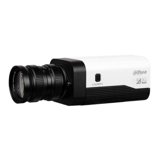
- Page 1 4K (8MP) Network Box Camera DH-IPC-HF8835FN Quick Start Guide Version 001.001 Dahua Technology USA Inc.
-
Page 2: Table Of Contents
Table of Contents Welcome........................1 Important Safeguards and Warnings..............1 Electrical safety ....................1 Environmental Precautions ................2 Operation and Daily Maintenance ..............3 Warnings ......................3 FCC Information ....................4 FCC compliance: .................... 4 Legal Notices ....................4 Copyright ......................4 Trademarks ....................... -
Page 3: Welcome
This manual offers reference material and general information about the basic operation, maintenance, and troubleshooting of this Dahua camera. Read, follow, and retain the following safety instructions. Heed all warning on the unit and in the operating instructions before operating the unit. -
Page 4: Environmental Precautions
Ensure a service technician uses replacement parts specified by the manufacturer, or that have the same characteristics as the original parts. Unauthorized parts may cause fire, electrical shock, or other hazards. Dahua is not liable for any damage or harm caused by unauthorized modifications or repairs. -
Page 5: Operation And Daily Maintenance
• Dahua recommends the use of a thunder-proof device in concert with the unit. • Do not touch the CCD or the CMOS optic sensor. Use a blower to clean dust or dirt on the lens surface. -
Page 6: Fcc Information
1.3 Legal Notices Copyright This user guide is ©2017, Dahua Technology Company, LTD. This user guide is the intellectual property of Dahua Technology Company, LTD and is protected by copyright. All rights reserved. Trademarks All hardware and software product names used in this document are likely to be registered trademarks and must be treated accordingly. -
Page 7: Unpacking
2 Unpacking This equipment should be unpacked and handled with care. If an item appears to have sustained damage during shipping, notify the shipper immediately. Verify that all the parts listed below are included. If an item is missing, contact customer support or your local representative. -
Page 8: Installation And Configuration
3 Connections and Configuration 3.1 Camera Connections Figure 3-1 Port Name Port Function Power IN 24 VAC, 12 VDC Input 24 VAC or 12 VDC Ground end of RS232 serial port. Send signal to RS232 serial port. RS232 port Receive signal from RS232 serial port. RS485_A port control for external PTZ. -
Page 9: Framework And Dimensions
Certain cameras include a SDHC card slot for onboard storage that support a 128 GB Micro SD card. Dahua recommends using a SanDisk Extreme Micro SD card (or an equivalent substitute) as these cards have been fully tested without issue and the SanDisk Extreme line is better suited for constant recording. -
Page 10: Alarm Setup
3.5 Alarm Setup Certain devices support alarm inputs and outputs, check your specific device for alarm capability. Alarm Input Refer to Figure 3-3 for alarm input configuration. The device collects that status of the alarm input port when the input signal is idle or grounded. If the input signal is connected to the 3.3 V or it is idle then the device receives the alarm input signal. - Page 11 5. Navigate to the Alarm page, under the Event menu item. Figure 3-5 Set the alarm input and output parameters. Set the Sensor Type to NO or NC for each alarm input. The alarm input set corresponds to the device I/O port cable. When an alarm is triggered, the alarm input device generates a high- and low-level signal.
-
Page 12: Device Installation
4 Device Installation This section detail installing various components of the camera. DO NOT connect the camera to the power supply during installation. The following installation diagram is for reference only. Please refer to the illustration that corresponds to your particular camera. Figure 4-1 4.1 Installing an Auto-Iris Lens 1. -
Page 13: Installing An Sd Card
4.3 Installing an SD Card 1. Remove protective cover from the SD Card slot. 2. Insert the SD Card into the rear of the camera. 3. Replace the protective cover. Figure 4-2 4.4 Installing Cables to I/O Ports Figure 4-3 1. -
Page 14: Mounting The Camera
4.5 Mounting the Camera This box camera requires a separate mount for installation to a wall or to a ceiling. Refer to the specific installation instructions for each mount. Product Number Description Image PFB110W Wall/Ceiling Mount PFB121W Wall Mount... -
Page 15: Network Configuration
5 Network Configuration Dahua IP cameras feature a built-in Web interface to control all aspects of camera operation. This section includes details about the supported network protocols, configuring IP addresses, and configuring alarms and local recording options. Refer to the camera’s Operations Manual for full details. -
Page 16: Modifying The Ip Address
Port – A port is an endpoint to a logical connection in an IP network. Dahua supplies the ConfigTool to access and to modify the network settings of a device. Refer to the Operation Manual, available on the CD included with the camera or on Dahuasecurity.com, for complete information. -
Page 17: Accessing The Web Interface
6. Click the Net icon at the top of the ConfigTool. 7. Modify the IP Address and any other applicable network parameter. 8. Click Save to finish modification and store the modified network parameters. Figure 5-2 5.4 Accessing the Web Interface Each camera can be accessed directly from the Internet Explorer Web browser. -
Page 18: Configuring Local Sd Card Recording
3. Install the controls according to the system prompt. Once the controls are installed IE displays the Web Interface main page. 4. Modify the administrator password as soon as possible after you successfully logged in. 5.5 Configuring Local SD Card Recording The devices Web interface contains settings to control the recording medium and to configure an alarm that triggers once the Micro SD card passes a pre-determined storage. - Page 19 4. Expand the Event menu, located at the left of the Web interface, then select the Abnormality page to set alarms related to the Micro SD card. The contains the following Micro SD card alarm options: • No SD Card: Device triggers an alarm if the device does not contain a Micro SD card. •...
- Page 20 Dahua Technology USA Inc. 23 Hubble, Irvine, CA 92618 Tel: (949) 679-7777 Fax: (949) 679-5760 Email: sales.usa@global.dahuatech.com Rev 001.001 © 2018 Dahua. All rights reserved. Design and specifications are subject to change without notice.
Need help?
Do you have a question about the DH-IPC-HF8835FN and is the answer not in the manual?
Questions and answers