Table of Contents
Advertisement
Quick Links
OPERATOR MANUAL
MAT 55-20, MAT 75-15, MAT 100-10, MAT 150-7
KEPCO INC.
An ISO 9001 Company.
IMPORTANT NOTES:
1)
This manual is valid for the following Model and associated serial numbers:
MODEL
MAT 55-20
MAT 75-15
MAT 100-10
MAT 150-7
2)
A Change Page may be included at the end of the manual. All applicable changes and
revision number changes are documented with reference to the equipment serial num-
bers. Before using this Instruction Manual, check your equipment serial number to identify
your model. If in doubt, contact your nearest Kepco Representative, or the Kepco Docu-
mentation Office in New York, (718) 461-7000, requesting the correct revision for your par-
ticular model and serial number.
3)
The contents of this manual are protected by copyright. Reproduction of any part can be
made only with the specific written permission of Kepco, Inc.
Data subject to change without notice.
©2018, KEPCO, INC
P/N 243-1396
KEPCO, INC. 131-38 SANFORD AVENUE FLUSHING, NY. 11355 U.S.A. TEL (718) 461-7000 FAX (718) 767-1102
MAT 1080W, FULL RACK
POWER SUPPLY
HIGH VOLTAGE MODELS:
MODEL
MAT 1080W
POWER SUPPLY
ORDER NO.
SERIAL NO.
email: hq@kepcopower.com World Wide Web: http://www.kepcopower.com
REV. NO.
REV. NO.
KEPCO
THE POWER SUPPLIER™
®
Advertisement
Table of Contents

Related Manuals for KEPCO MAT Series


Summary of Contents for KEPCO MAT Series
- Page 1 Data subject to change without notice. KEPCO ® ©2018, KEPCO, INC THE POWER SUPPLIER™ P/N 243-1396 KEPCO, INC. 131-38 SANFORD AVENUE FLUSHING, NY. 11355 U.S.A. TEL (718) 461-7000 FAX (718) 767-1102 email: hq@kepcopower.com World Wide Web: http://www.kepcopower.com...
- Page 3 There are no user or operator serviceable parts within the product enclosure. Refer all servicing to qualified and trained Kepco service technicians. 228-1351 COND/CONFORM 101718...
- Page 4 SAFETY INSTRUCTIONS 1. Installation, Operation and Service Precautions This product is designed for use in accordance with EN 61010-1 and UL 3101 for Installation Category 2, Pollution Degree 2. Hazardous voltages are present within this product during normal operation. The prod- uct should never be operated with the cover removed unless equivalent protection of the operator from accidental contact with hazardous internal voltages is provided: There are no operator serviceable parts or adjustments within the product enclosure.
-
Page 5: Table Of Contents
TABLE OF CONTENTS SECTION PAGE SECTION 1 - INTRODUCTION Scope Of Manual............................. 1-1 General Description..........................1-1 Specifications, Electrical.......................... 1-3 DC Output Ratings For 1/3, 2/3 And Full Rack Modules ................. 1-4 Miscellaneous Features .......................... 1-8 Accessories ............................. 1-8 Safety ..............................1-9 SECTION 2 - INSTALLATION Unpacking And Inspection........................ - Page 6 FIGURE TITLE PAGE Remotely Controlled Power Supply Configurations Using Kepco Products..........1-2 MAT Power Module Mechanical Outline Drawing ..................1-6 The TMA 4882-27 Controller And MAT Power Modules ................1-9 Front View Of The Full Rack MAT Power Supply ..................2-3 Rear View Of The MAT Full Rack Power Module ..................
- Page 7 LIST OF TABLES TABLE TITLE PAGE MAT Power Module Features And Specifications ..................1-3 MAT Power Modules Power Output Ratings ....................1-5 Safety Symbols ............................1-9 Internal Controls Accessible Through Top Cover ..................2-1 Front Control MAT Power Module ......................2-2 Rear Terminations, MAT Power Module .....................2-3 DC Output Connector Pin Functions ......................2-3 Input And Output Connectors ........................2-4 Internal Jumper Configuration ........................2-9...
-
Page 9: Section 1 - Introduction
The MAT Power Module can also be directly controlled via the keypad of the MBT Series (“G” Option) Power Supply via the IEEE 1118 bus. An important feature of the MAT Series Power Module is the overvoltage and overcurrent pro- tection circuits. This protection is provided by two autotracking amplifiers that have an overvolt- age and overcurrent tracking range of 10% ±... - Page 10 MAT FULL RACK 101718...
-
Page 11: Specifications, Electrical
Leakage Current Output to chassis A rms or 50 A p-p @ 115V a-c Series/Parallel Operation Consult Kepco application engineering 3-1/2 digit LCD Output Display Switch selectable voltage/current Panel Meter Voltage and Current Mode,Output Enabled, Polarity IndIcators 4 LEDs... -
Page 12: Dc Output Ratings For 1/3, 2/3 And Full Rack Modules
TABLE 1-1. MAT POWER MODULE FEATURES AND SPECIFICATIONS (CONTINUED) MAT POWER MODULE PARAMETER CONDITION 1/3 RACK 2/3 RACK FULL RACK Overvoltage Tracks program voltage, Crowbars output and turns off input Overcurrent Tracks program current, Crowbars output and turns off input Monitors heat sink temperature, Crowbars output and turns Protection Overtemperature... - Page 13 TABLE 1-2. MAT POWER MODULES POWER OUTPUT RATINGS MODEL VOLTS AMPS POWER (Range) Range (Nominal) 360W MODULES-1/3 RACK SIZE-DC OUTPUT RATINGS MAT 6-32 0-32 MAT 15-20 0-15 0-20 MAT25-14 0-25 0-14 MAT 36-10 0-36 0-10 MAT 55-7 0-55 MAT 75-5 0-75 MAT 100-3.6 0-100...
- Page 14 FIGURE 1-2. MAT POWER MODULE MECHANICAL OUTLINE DRAWING (SHEET 1 OF 2) MAT FULL RACK 101718...
- Page 15 FIGURE 1-2. MAT POWER MODULE MECHANICAL OUTLINE DRAWING (SHEET 2 OF 2) MAT FULL RACK 101718...
-
Page 16: Miscellaneous Features
One 2 meter long shielded twisted pair cable with two DIN mating connectors (see Table 2- 5), one at each end (Kepco P/N 118-0699) is supplied with each Rack Adapter (RA 50 or RA 51) and with each Full Rack MAT Power Module. The Power Module Controller (see PAR. -
Page 17: Safety
There are no operator serviceable parts inside the case. Service must be referred to authorized personnel. Using the power supply in a manner not specified by Kepco. Inc. may impair the pro- tection provided by the power supply. Observe all safety precautions noted throughout this man- ual. -
Page 19: Section 2 - Installation
SECTION 2 - INSTALLATION UNPACKING AND INSPECTION This instrument has been thoroughly inspected and tested prior to packing and is ready for operation. After careful unpacking, inspect for shipping damage before attempting to operate. Perform the preliminary operational check as outlined in PAR 2.8 If any indication of damage is found, file an immediate claim with the responsible transport service. - Page 20 TABLE 2-2. FRONT CONTROL MAT POWER MODULE ITEM NO. CONTROL FUNCTION (See Fig. 2-1) AC POWER Switch/circuit Breaker Serves as an a-c power switch and turns the ac power line off on overvoltage, overcurrent, over- temperature or power loss. CAUTION: DO NOT repeatedly toggle the Switch/circuit Breaker as this may cause unit to fault.
-
Page 21: Front View Of The Full Rack Mat Power Supply
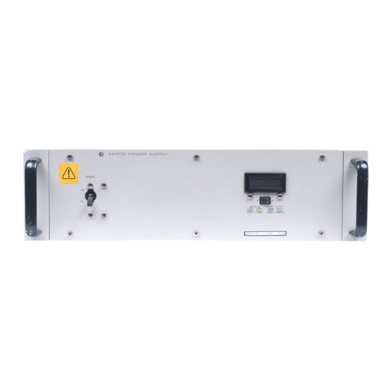
FIGURE 2-1. FRONT VIEW OF THE FULL RACK MAT POWER SUPPLY TABLE 2-3. REAR TERMINATIONS, MAT POWER MODULE ITEM NO. REAR TERMINATION FUNCTION (See Fig. 2-2) DC OUTPUT Connects the MAT power module output lines, sensing lines and ground line to CONNECTOR the load (connector supplied). -
Page 22: Ac Input Requirement
TABLE 2-5. INPUT AND OUTPUT CONNECTORS CHASSIS MOUNT MATING PLUG AC INPUT CONNECTOR (MIL STD CONNECTOR, MS TYPE OR EQUIVALENT) MS3108A16--10S MS3102A16-10P (KEPCO P/N 143-0331) DC OUTPUT CONNECTORS (MIL STD CONNECTOR, MS TYPE OR EQUIVALENT) M3102A28-20P M3102A28-20S (KEPCO P/N 143-0321) DIGITAL BUS CONNECTOR... -
Page 23: Cooling
NOTE: Do not move the wires connected to the barrier strip, they are properly placed for both 115 Va-c and 230 Va-c operation. Figure 2-3A shows the barrier terminal block set to 115 Va-c operation. Remove the jump- ers on the barrier strip connecting terminals 2 to 3, and terminals 4 to 5. Place a jumper between terminals 3 and 4. -
Page 24: Grounding
National and international safety standards set procedures for the grounding of a metal cover and chassis of an instrument connected to an ac power source. The MAT Power Module is supplied with an ac female plug (MS3106A16-10S, Kepco P/N 143- 0331), that mates with a chassis mounted male receptacle (MS3102A16-10P. Kepco P/N 142- 0268). - Page 25 FIGURE 2-4. VARIATION OF OUTPUT IMPEDANCE WITH FREQUENCY FOR A VOLTAGE SOURCE AND A CURRENT SOURCE A practical model for a voltage stabilized Power Module includes a series inductance represent- ing dc and low frequency source impedance. Load leads should have minimum voltage drops (error sensing is discussed below) and minimum inductance (error sensing does not compen- sate for this).
-
Page 26: Load Connection, Local Error Sensing
2.6.5 LOAD CONNECTION WITH REMOTE ERROR SENSING The MAT series of Power Modules can operate with sensing external to the Module. Sensing should be with a twisted wire pair to reduce noise. The sensing wires must be connected as fol- lows: Output terminal 1 to Sense Terminal 1 and Output Terminal 2 to Sense Terminal 2, each at the load (see Figure 2-6). -
Page 27: Operating Configuration
In this procedure the MAT Power Module Control Bus address is 3, (it is set at the factory to 3). Connect the Kepco Power Module Controller and the MAT Power Module (following check-out uses a MAT Power Module Model 100-10 as an example) to the Control Bus. Connect the Host Computer and the Power Module Controller to the IEEE 488 GPIB. -
Page 28: Example 1: Full Scale Voltage Check
Device Clear Interface Function via the Host Computer. For proper time delays between com- mands refer to PAR. 3.4. For details on the CIIL commands refer to PAR. 3.6.3 and Appendix C as well as the Power Module Controller Manual. The following does not include the IEEE 488 Bus Commands. -
Page 29: Example 2: Full Scale Current Check
INX VOLT(cr)(lf) The MAT previously set up now starts to measure and send the proper time delay needed for the measurement. The Power Module Controller will send the time delay value back to the Host Computer when it has been properly Talk Addressed (see specific IEEE 488 interface require- ments): 00(cr)(lf) 10. -
Page 30: Example 3: To Reset The Power Module
The MAT previously set up now starts to measure and send the proper time delay needed for the measurement. The Power Module Controller will send the time delay value back to the Host Computer when it has been properly Talk Addressed (see specific IEEE 488 interface require- ments): 00(cr)(lf) The Host Computer then sends:... -
Page 31: Section 3 - Operation
(see Figures 3-1 and 3-2 and Table 3-1). This address is set at Kepco to 3. The MAT family of Power Modules is controlled by the Power Module Controller (see PAR. 1.2). - Page 32 TABLE 3-1. DEVICE ADDRESS SELECTION FOR THE MAT POWER MODULE DECIMAL A3S1-4 A3S1-3 A3S1-2 A3S1-1 A3S1-0 ADDRESS (A4) (A3) (A2) (A1) (A0) MAT FULL RACK/ 101718...
-
Page 33: Mat/Power Module Controller System
Power for the microcomputer board of the TMA 4882-27 Power Module Controller is provided by a wide range input Power Supply, Kepco Model MRW 150KV. The AC input voltage can range from 95 Volts AC to 264 Volts AC, thereby eliminating the need for an input voltage selector. -
Page 34: Automatic (Tracking) Control Of The Crowbar Level
command causes noncatastrophic error messages to be stacked in memory until interrogated by a Status command. AUTOMATIC (TRACKING) CONTROL OF THE CROWBAR LEVEL MAT Power Modules have Overvoltage and Overcurrent Tracking Amplifiers. These amplifiers will cause a crowbar flag, send a catastrophic error to the Power Module Controller and shut the module down if the output goes out of tolerance. -
Page 35: Remote Programming
REMOTE PROGRAMMING 3.6.1 GENERAL Kepco MAT Power Supplies are programmed over a control bus using either SCPI (Standard Commands for Programmable Instruments) or CIIL (Control Interface Intermediate Language) commands. SCPI and CIIL provide a common language conforming to IEEE488.2 for instru- ments used in an automatic test system. -
Page 36: Scpi Programming
For the complete command set, and detailed SCPI programming information, consult the Technical Manual for the applicable controller (the SCPI command sets among Kepco con- trollers are slightly different). See PAR.3.2 to establish the MAT power supply Control Bus (BIT- BUS) address. - Page 37 /**************************************************************************/ Sample Program For KEPCO power supply, using National Instruments GPIB interface card and IBM PC or compatible computer /**************************************************************************/ #include <stdio.h> #include "decl.h" char rd_str[80]; // Input buffer char dat_str[80]; // Output buffer bd,adr; main() { adr = ibfind("DEV6");...
-
Page 38: Ciil Programming
3.6.3 CIIL PROGRAMMING The CIIL command language is used on early models of Kepco power supplies and controllers. The command functions are included here for compatibility with other equipment programmed with CIIL commands. The CIIL command set for the MAT Power Supply is defined and explained in Appendix A. - Page 39 2. To verify the previous command was implemented the Host Computer sends: STA(cr)(lf) The Power Module Controller sends back (if no errors occur) (sp)(cr)(lf) 3. To close the Output Enable relay (connects the Power Module to the load) the Host Com- puter sends: :CH9(sp)(lf) The Power Module at address 9, closes the relay...
-
Page 40: 3.6.3.1.2 Example 2: Program Negative Voltage With Current Limit
8. To open the Output Enable relay (disconnect the load from the Power Module), the Host Computer sends: :CH9(cr)(lf) The Power Module relay at address 9 is open 9. To verify the previous command was implemented, the Host Computer sends: STA(cr)(lf) The Power Module Controller sends back (if no errors occur) (sp)(cr)(lf) -
Page 41: 3.6.3.1.3 Example 3: Program Current And Voltage Limit
6. To take reading the Host Computer sends: VOLT(cr)(lf) The MAT previously set up now starts to measure and sends the proper time delay needed for the measurement The Power Module Controller will send the time delay back to the Host Computer when it has been Talk Addressed (see specific IEEE 488 interface requirements): 00(cr)(lf) 7. -
Page 42: Mat Calibration Procedure
3. To enable the output, the Host Computer sends: :CH9(cr)(lf) 4. To verify the previous command was implemented the Host Computer sends: STA(cr)(lf) The Power Module Controller sends back (if no errors occur): (sp)(cr)(lf) 5. To measure the current at the output the Host Computer sends: CURR :CH9(cr)(lf) The MAT at address 9 is now set to take a reading... -
Page 43: E/I Zero Calibration
NOTE: E and I must be replaced with numerical values that represent the maximum o max o max output voltage (E ) and maximum output current (I ) respectively of the unit o max o max under test. For example, for a MAT 100-10 unit E = 100 Vdc and I = 10 A. - Page 44 7. Send the following commands to set current to 0 and voltage limit to E o max SCPI COMMANDS CIIL COMMANDS FUNC1:MODE CURR FNC DCS :CH1 SET CURR 0 SET VLTL E o max VOLT1 E o max ; CURR1 0; 8.
-
Page 45: E/I Full Scale Calibration
3.7.2 E/I FULL SCALE CALIBRATION The following procedure requires that E/I zero calibration (PAR. 3.7.1) be performed first. 1. Connect a precision Digital Voltmeter to the rear output Connector Error Sensing termi- nals (see Figure 3-2 and Table 3-2). At this time the load should be disconnected and the Error Sensing terminals should be connected to the corresponding power output ter- minals. - Page 46 10. Adjust R16 until the measured output current by the external ammeter is omax ----------------- - omax 2x4095 11. Disable the output by sending Reset command SCPI COMMANDS CIIL COMMANDS *RST 12. Disconnect the Digital Ammeter and the Digital voltmeter. 3-16 MAT FULL RACK/ 101718...
-
Page 47: Fnc - Function Command
APPENDIX A - CIIL COMMAND DEFINITIONS INTRODUCTION This appendix defines the CIIL commands used with the MAT Power Supply. Table A-1 provides a quick reference of all CIIL commands used in the MAT Power Supply. TABLE A-1. CIIL SUBSYSTEM COMMAND/QUERY INDEX COMMAND PAGE COMMAND... -
Page 48: Inx - Initiate Op Code Command
Syntax: INX VOLT (initiate voltage reading) INX CURR (initiate current reading) Function: Commences a data acquisition process in accordance with the preceding FNC command. Description: The response to the INX command is a dynamic time-out value, unless a catastrophic error condition exists, in which case an error message will be returned. -
Page 49: Set Command
VOLT or CURR value so that the power supply's polarity may be selected. In the case of Kepco's MAT power supplies, the two related Op Codes, SRX and SRN are functionally identical to the SET command, since there is only one range, 0 - maximum. The commands are included only for compatibility. -
Page 50: Rst - Reset Command
OPN, CLS Syntax: OPN :CHnn CLS :CHnn Function: These commands are used to connect or disconnect the power supply from the load (effective for MR and MGR options only). Description: Disconnects the load from the power supply specified by the operand. Connects the load to the power supply specified by the operand. - Page 51 Syntax: Function: Causes power supply to return operating status to controller. Description: This operator commands the power supply to report its present operating status. Status is reported in the form of a message (character string) as defined below. Any catastrophic error conditions (indicated by * in the table below) which exist will be reported, until the error condition is corrected.
Need help?
Do you have a question about the MAT Series and is the answer not in the manual?
Questions and answers