Table of Contents
Advertisement
Quick Links
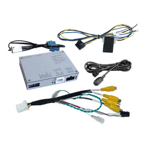
Video inserter
RL4-MBN6
Compatible with Mercedes Benz vehicles with
MBUX/NTG6 with 7inch or 10.25inch monitor
Video-inserter for front- and rear-view camera
and two more video inputs
Product features
• Video-inserter for factory-infotainment systems
• 1 CVBS Input for rear-view camera
• 1 CVBS Input for front camera
• 2 CVBS Video-inputs for after-market Video sources (e.g. DVD-Player, DVB-T Tuner)
• Automatic switching to rear-view camera input on engagement of the reverse gear
• Automatic front camera switching after reverse gear for 10 seconds
• Activatable parking guide lines for rear-view camera (not available for all vehicles)
• Video-in-motion (ONLY for connected video-sources)
• Video-inputs NTSC and PAL compatible
Version 26.07.2022 HW:CAM(V98/99/100)/(V45/46) + HW: CAM(V100)/(V47.3/LG) + CAM(V100)/(V20) + CAM(V100)/(V81)
RL4-MBN6
Advertisement
Table of Contents

Related Manuals for Car-Interface RL4-MBN6


Summary of Contents for Car-Interface RL4-MBN6
- Page 1 Video inserter RL4-MBN6 Compatible with Mercedes Benz vehicles with MBUX/NTG6 with 7inch or 10.25inch monitor Video-inserter for front- and rear-view camera and two more video inputs Product features • Video-inserter for factory-infotainment systems • 1 CVBS Input for rear-view camera •...
-
Page 2: Table Of Contents
Settings of the 4 Dip switches (CAN function – red) 2. Installation 2.1. Place of connection 2.1.1. Removing the MBUX head-unit in the Sprinter (W907) 2.1.2. Place of installation – RL4-MBN6 2.2. Connection schema 2.3. Connection 2.3.1. Picture signal cable - Head unit type 1 2.3.2. -
Page 3: Prior To Installation
Due to changes in the production of the vehicle manufacturer there’s always a possibility of incompatibility. 1.1. Delivery contents Take down the serial number of the interface and store this manual for support purposes: ____________________ Version 26.07.2022 HW:CAM(V98/99/100)/(V45/46) + HW: CAM(V100)/(V47.3/LG) + CAM(V100)/(V20) + CAM(V100)/(V81) RL4-MBN6... -
Page 4: Checking The Compatibility Of Vehicle And Accessories
"Case 2: Interface does not receive a reverse gear signal"). Vehicles with active Park assistant system 235 While the factory active park assistant system 235 is in use, the displaying of the camera picture is not possible. Version 26.07.2022 HW:CAM(V98/99/100)/(V45/46) + HW: CAM(V100)/(V47.3/LG) + CAM(V100)/(V20) + CAM(V100)/(V81) RL4-MBN6... -
Page 5: Boxes And Connectors - Video Interface
There are 2 different interface versions: ➢ Version with 6-dip switches on the top of the housing ➢ Version without 6-dip switches on the top of the housing Version 26.07.2022 HW:CAM(V98/99/100)/(V45/46) + HW: CAM(V100)/(V47.3/LG) + CAM(V100)/(V20) + CAM(V100)/(V81) RL4-MBN6... -
Page 6: Settings Of The 8 Dip Switches (Black)
If set to OFF, the video interfaces’ red wire will supply permanent +12V ACC (max 3A). Description of the power supply output: see chapter “Power supply output”. Version 26.07.2022 HW:CAM(V98/99/100)/(V45/46) + HW: CAM(V100)/(V47.3/LG) + CAM(V100)/(V20) + CAM(V100)/(V81) RL4-MBN6... -
Page 7: Enabling The Interface's Video Inputs (Dip 2-3)
Disconnect the 10pin plug at the interface box between every change of the dip setting. After each Dip-switch-change a power-reset of the interface box has to be performed! Version 26.07.2022 HW:CAM(V98/99/100)/(V45/46) + HW: CAM(V100)/(V47.3/LG) + CAM(V100)/(V20) + CAM(V100)/(V81) RL4-MBN6... -
Page 8: Settings Of The 4 Dip Switches (Can Function - Red)
Note: During the use of the factory active park assistant system 235, no camera image is available. After each Dip-switch-change a power-reset of the interface-box has to be performed! Version 26.07.2022 HW:CAM(V98/99/100)/(V45/46) + HW: CAM(V100)/(V47.3/LG) + CAM(V100)/(V20) + CAM(V100)/(V81) RL4-MBN6... -
Page 9: Installation
2.1.1. Removing the MBUX head-unit in the Sprinter (W907) Remove air vents by using MB special tool. Remove one hidden screw under each air vents Remove front cover – monitor will stay in front. Remove the head-unit. Version 26.07.2022 HW:CAM(V98/99/100)/(V45/46) + HW: CAM(V100)/(V47.3/LG) + CAM(V100)/(V20) + CAM(V100)/(V81) RL4-MBN6... -
Page 10: Place Of Installation - Rl4-Mbn6
2.1.2. Place of installation - RL4-MBN6 The installation of the interface box close to or behind the MBUX head unit should generally be avoided in all vehicles due to thermal problems, as the head-unit has a very high heat generation. -
Page 11: Connection Schema
2.2. Connection schema Version 26.07.2022 HW:CAM(V98/99/100)/(V45/46) + HW: CAM(V100)/(V47.3/LG) + CAM(V100)/(V20) + CAM(V100)/(V81) RL4-MBN6... -
Page 12: Connection
2.3. Connection Version 26.07.2022 HW:CAM(V98/99/100)/(V45/46) + HW: CAM(V100)/(V47.3/LG) + CAM(V100)/(V20) + CAM(V100)/(V81) RL4-MBN6... -
Page 13: Picture Signal Cable - Head Unit Type
Attention: The picture signal cabel’s connection has always to be done at the head unit’s Double Fakra, even if only one side of the factory Double Fakra is occupied! Version 26.07.2022 HW:CAM(V98/99/100)/(V45/46) + HW: CAM(V100)/(V47.3/LG) + CAM(V100)/(V20) + CAM(V100)/(V81) RL4-MBN6... -
Page 14: Picture Signal Cable Head Unit Type
Double Fakra connector and connect it to the male waterblue coloured double Fakra connector of the enclosed picture signal cable. Connect the picture signal cable’s waterblue coloured female Double-Fakra connector to the head-unit’s previously become free green coloured Double-Fakra connector. Version 26.07.2022 HW:CAM(V98/99/100)/(V45/46) + HW: CAM(V100)/(V47.3/LG) + CAM(V100)/(V20) + CAM(V100)/(V81) RL4-MBN6... -
Page 15: 10Pin Power/Can Cable
10pin power / CAN cable to the vehicle’s CAN-Low Connect the blue wire of the 10pin Power / CAN Cable to the vehicle’s CAN-High. Connection diagrams: see next chapter Version 26.07.2022 HW:CAM(V98/99/100)/(V45/46) + HW: CAM(V100)/(V47.3/LG) + CAM(V100)/(V20) + CAM(V100)/(V81) RL4-MBN6... -
Page 16: Installation With Connection To Can Bus Or Analogue (Without Can Bus)
2.3.4. Installation with connection to CAN bus or analogue (without CAN bus) The RL4-MBN6 can be integrated via CAN bus as well as operated in analogue mode without CAN bus. When integrated via CAN bus, the interface is switched on by the vehicle’s CAN-Bus and the R-gear signal is usually recognised, too (not all vehicles). -
Page 17: Alternative Connection Point Power/Can - Sprinter W907/910
Ground black brown There`s no liability for the vehicle`s pin diagram! Changes in the manufacturer`s production are possible any time. The mentioned information has to be verified by the installer. Version 26.07.2022 HW:CAM(V98/99/100)/(V45/46) + HW: CAM(V100)/(V47.3/LG) + CAM(V100)/(V20) + CAM(V100)/(V81) RL4-MBN6... -
Page 18: Installation With Analogue Connection (Without Can-Bus)
With analogue connection of the video interface (without CAN bus), the connection of the rear-view camera must also be made manually. (see point 2.3.5.2.: Case 2: Interface does not receive a reverse gear signal). Version 26.07.2022 HW:CAM(V98/99/100)/(V45/46) + HW: CAM(V100)/(V47.3/LG) + CAM(V100)/(V20) + CAM(V100)/(V81) RL4-MBN6... -
Page 19: After-Market Rear-View Camera
CAN bus. In this case, connect the rear-view camera as described in the following chapter "Case 2". Version 26.07.2022 HW:CAM(V98/99/100)/(V45/46) + HW: CAM(V100)/(V47.3/LG) + CAM(V100)/(V20) + CAM(V100)/(V81) RL4-MBN6... -
Page 20: Case 2: Interface Does Not Receive The Reverse Gear Signal
Connect the output connector (87) of the relay to the rear-view camera’s power- cable, like you did it to the green “Reverse-IN” cable before. Connect stabile and permanent +12V to the relay’s input connector (30). Version 26.07.2022 HW:CAM(V98/99/100)/(V45/46) + HW: CAM(V100)/(V47.3/LG) + CAM(V100)/(V20) + CAM(V100)/(V81) RL4-MBN6... -
Page 21: Power Supply Output
Note: In addition, a manual switch-over to the front camera input is possible via keypad (short press) from any image mode. The power supply output supplies +12V then, too (if Dip 1 is set to ON and the front camera input is selected). Version 26.07.2022 HW:CAM(V98/99/100)/(V45/46) + HW: CAM(V100)/(V47.3/LG) + CAM(V100)/(V20) + CAM(V100)/(V81) RL4-MBN6... -
Page 22: Connection - Video-Interface And External Keypad
Connect the female 4pin connector of the keypad to the male 4pin connector of the 12pin interface cable. Note: Even if switching through several video sources by the keypad mightn’t be required, the invisible connection and availability is strongly recommended. Version 26.07.2022 HW:CAM(V98/99/100)/(V45/46) + HW: CAM(V100)/(V47.3/LG) + CAM(V100)/(V20) + CAM(V100)/(V81) RL4-MBN6... -
Page 23: Connection - Video-Sources
Connect the front camera’s video RCA connector to the 12pin interface cable’s female RCA connector „Front V3“. Connect the video RCA of the AV source 1 and 2 to the 12pin interface cable’s female RCA connector “Left (V1)” ”Right (V2)”. Version 26.07.2022 HW:CAM(V98/99/100)/(V45/46) + HW: CAM(V100)/(V47.3/LG) + CAM(V100)/(V20) + CAM(V100)/(V81) RL4-MBN6... -
Page 24: Audio Insertion
Guide L Move guide lines horizontally (when left out - right back in) Guide R (no function) UI-CNTRL (no function - guide lines only for 7inch by dip switch 6) Size H/V (picture size horizontal/vertical) Version 26.07.2022 HW:CAM(V98/99/100)/(V45/46) + HW: CAM(V100)/(V47.3/LG) + CAM(V100)/(V20) + CAM(V100)/(V81) RL4-MBN6... - Page 25 Note: If there is no communication between interface and the vehicle`s CAN-bus (several vehicles aren’t compatible), the reverse gear guide-lines can`t be shown during the vehicle’s operation even if they once appear after having switched the system to powerless! Version 26.07.2022 HW:CAM(V98/99/100)/(V45/46) + HW: CAM(V100)/(V47.3/LG) + CAM(V100)/(V20) + CAM(V100)/(V81) RL4-MBN6...
-
Page 26: Interface Operation
270mA @12V Video input 0.7V - 1V Video input formats NTSC/PAL Temperature range -40°C to +85°C Dimensions video-box 119 x 24 x 100 mm (W x H x D) Version 26.07.2022 HW:CAM(V98/99/100)/(V45/46) + HW: CAM(V100)/(V47.3/LG) + CAM(V100)/(V20) + CAM(V100)/(V81) RL4-MBN6... -
Page 27: Faq - Trouble Shooting-Interface Functions
Test camera under natural light outside the garage. flickers. directly into the camera. Camera input picture is Protection sticker not Remove protection sticker from lens. bluish. removed from camera lens. Version 26.07.2022 HW:CAM(V98/99/100)/(V45/46) + HW: CAM(V100)/(V47.3/LG) + CAM(V100)/(V20) + CAM(V100)/(V81) RL4-MBN6... -
Page 28: Technical Support
NavLinkz GmbH. For products bought from other sources, contact your vendor for technical support. NavLinkz GmbH distribution/tech dealer-support Heidberghof 2 D-47495 Rheinberg +49 2843 17595 00 Email mail@navlinkz.de 10R-05 0068 Made in China Version 26.07.2022 HW:CAM(V98/99/100)/(V45/46) + HW: CAM(V100)/(V47.3/LG) + CAM(V100)/(V20) + CAM(V100)/(V81) RL4-MBN6...
Need help?
Do you have a question about the RL4-MBN6 and is the answer not in the manual?
Questions and answers