Table of Contents
Advertisement
Quick Links
Advertisement
Table of Contents

Subscribe to Our Youtube Channel
Related Manuals for TKO 7010-G2


Summary of Contents for TKO 7010-G2
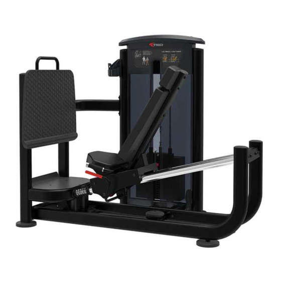
- Page 1 7010-G2 LEG PRESS/CALF RAISE Owner's Manual...
-
Page 2: Table Of Contents
Table Of Contents CAUTION! Read all precautions and instructions in this manual before using this equipment. Important Safety Instructions----------------------------------------------------------- 3 Instructions-------------------------------------------------------------------------------- 5 Exploded View and Parts List------------------------------------------------------------ 6 Measurement Guide--------------------------------------------------------------------- 19 Assembly Instructions------------------------------------------------------------------ 20 Assembly--------------------------------------------------------------------------------- 21 Adjust Instructions---------------------------------------------------------------------- 34 Exercise Instructions-------------------------------------------------------------------- 35 Maintenance Schedule------------------------------------------------------------------ 36 General Maintenance Information----------------------------------------------------- 37 Weight Training Tips-------------------------------------------------------------------- 38... -
Page 3: Important Safety Instructions
Important Safety Instructions Before beginning any fitness program, you should obtain a complete physical examination from your physician. When using exercise equipment, basic precautions should always be taken, including the following: 1. Read all instructions before using the equipment. These instructions are written to ensure your safety and to protect the unit. 2. - Page 4 Important Safety Instructions Personal Safety During Assembly Read each step in the assembly instructions and follow the steps in sequence. Do not skip ahead. If you skip ahead, you may learn later that you have to disassemble components and that you may have damaged the equipment. Assemble and operate the equipment on a solid, level surface.
-
Page 5: Instructions
Instructions Before beginning assembly please take the time to read instructions thoroughly. Please use the various lists in this manual to make sure that all parts have been included in your shipment. When ordering, use part number and description from the lists. -
Page 6: Exploded View And Parts List
Exploded View and Parts List Overall ItemNo. Grade No. Part No. Description IT951001ASSY Weight Stack Frame ASSY IT951002ASSY Main Frame ASSY IT95100300 Bottom Frame Brace IT951004ASSY Front Frame ASSY IT95100500 Front Connection Frame IT951005ASSY Seat Carriage Frame ASSY IT951006ASSY Assist Grip Frame ASSY IT951012ASSY Front Pedal ASSY IT95101000... - Page 7 Exploded View and Parts List Overall Item No. Grade No. Part No. Description IT95015600 Rear Shroud IT80023000 Weight Rubber Bumper IT90012000V1 Selector Pin W/Coil Guide Rod Fixing Sleeve φ 25* φ 19*45 IT95016100 HFOPT900-04A0602 Spring Spout Plug φ 16.5*6.88 IT95016500 IT95031300 Support Sleeve GB70BTM12*90DN18NL...
- Page 8 Exploded View and Parts List Overall...
- Page 9 Exploded View and Parts List Weight Stack Frame ASSY ItemNo. Grade No. Part No. Description IT95100100 Weight Stack Frame GB17880.5M6*16.5DS17 Rivet Nut M6 AC32705800 U-nut M6 IT95015700 Foot Plate IT95015900 Plastic Block Plug φ95*81.1 IT95015800 GB818M6*20DHS2 Cross Recessed Pan Head Screw M6*20...
- Page 10 Exploded View and Parts List Main Frame ASSY Grade No. Part No. Description ItemNo. IT95100200 Bottom Frame IT90013800P11C Plug RT50*100 IT95016400 Pulley Cover FE97122300 Limit Shaft IT95057800 4.5" Pulley Bushing φ22*φ17.5*7.5 FE97122100 Flat Washer φ11*φ25*2 DQ10N19B GB70BTM10*25DN18 Socket Head Cap Screw M10*25...
- Page 11 Exploded View and Parts List Front Frame ASSY Grade No. Part No. Description ItemNo. IT95100400 Front Frame GB17880.5M8*16.5DCS17 Rivet Nut M8 IT95102100 Urethane Bumper SG500110400V5 4.5" Pulley IT90013800P11C Plug RT50*100 GB70BTM10*55DN18 Socket Head Cap Screw M10*55 Flat Washer φ11*φ20*2 GB9510DN2 NM10DN2 Nylon Lock Nut M10...
- Page 12 Exploded View and Parts List Seat Carriage Frame ASSY Grade No. Part No. Description ItemNo. IT951007ASSY Adjustable Handle Frame ASSY IT951008ASSY Seat Frame ASSY IT951009ASSY Sliding Frame ASSY GB70M8*25N19 Socket Head Cap Screw M8*25 Flat Washer φ9*φ16*1.6 DQ8DS2B...
- Page 13 Exploded View and Parts List Adjustable Handle Frame ASSY ItemNo. Grade No. Part No. Description 6.1.1 IT95100700 Adjustable Handle Frame 6.1.2 IT95101100 6.1.3 FS522800 Grip 6.1.4 GB/T1243-199708BN19 Chain 6.1.5 SG80071200B Spring 6.1.6 KPS18002701V1 Nut M20*1.5*18 Sliding Frame ASSY Grade No. Part No. Description Item No .
- Page 14 Exploded View and Parts List Seat Frame ASSY Grade No. Part No. Description ItemNo. 6.2.1 IT95100800 Seat Frame 6.2.2 IT951010ASSY Roller Group1 6.2.3 IT951011ASSY Roller Group2 6.2.4 IT95101200 Eccentric Washer 6.2.5 IT95102300 Aluminum Tube Guide 6.2.6 IT95016300 Plastic Corner Tube Glide 6.2.7 IT90013800P11C Plug RT50*100...
- Page 15 Exploded View and Parts List Roller Group 1 Grade No. Part No. Description ItemNo. 6.2.2.1 IT95102200 6.2.2.2 BNH2472-01V1 Roller 6.2.2.3 BNH2472-03 Roller Spacer 6.2.2.4 FE97122100 Pulley Spacer1 Deep Groove Ball Bearing φ17*φ40*12 6.2.2.5 GB2766203-2Z Roller Group 2 Grade No. Part No. Description ItemNo.
- Page 16 Exploded View and Parts List Assist Grip Frame ASSY Grade No. Part No. Description ItemNo. IT95100600 Assist Grip Frame 026-01PL0206-5 Grip V39500 Aluminum Grip Cap V39600 Aluminum Grip Ring YZGB7710-32*3.2N19 Socket Set Screw 10-32UNF*3.2...
- Page 17 Exploded View and Parts List Front Pedal ASSY Cable1 ASSY Front Pedal ASSY ItemNo. Grade No. Part No. Description IT95101500 Front Pedal Frame FE97102000 Pedal Plate Cable1 ASSY Grade No. Part No. Description ItemNo. 11.1 IT95101801 Cable1 11.2 HF900-03A1002 Hex Flange Nut 11.3 HS11757602 Screw1/2"-13*50.8...
- Page 18 Exploded View and Parts List Back Pad ASSY ItemNo. Grade No. Part No. Description 16.1 IT95017100 Back Pad 16.2 IT95017300 Back Pad Cover 16.3 IT95017500 Back Pad Support Plate 16.4 GB70M10*15DS20 Socket Head Cap Screw M10*15 16.5 GB846ST4.2*19DHS Cross Recessed Countersunk Head Tapping Screw ST4.2*19 Head Pad ASSY Grade No.
-
Page 19: Measurement Guide
Measurement Guide BHCS = Button Head Cap Screw SHCS = Socket Head Cap Screw FHCS = Flat Head Cap Screw HHB = Hex Head Bolt CRPHS = Cross Recessed Pan Head Screw Millimeters Inches Diameter of bolt M6(1/4") M8(5/16") M10(3/8") M12(1/2") M16(5/8") (mm/inch) -
Page 20: Assembly Instructions
Assembly Instructions Assembly of the equipment takes professional installers about 2 hours. If this is the first time you have assembled this type of equipment, plan to spend more time. It is strongly recommended to assemble the equipment by professional installers. You may find it quicker, safer, easier to assemble this equipment with the help of a friend, as some of components may be large, heavy or awkward to handle alone. -
Page 21: Assembly
Assembly STEP 1 1. Attach four Adjustable Foot Plates (#19) to the Main Frame ASSY (#2) and Front Frame ASSY (#4). 2. Attach the Rear Bracket (#23) to the Top Rear Shroud (#28) using: two M6*10 CRPHS (#50) 3. Attach the Main Frame ASSY (#2) to the Front Frame ASSY (#4) using: four M12*80 SHCS (#39) two M12 Nylon Lock Nut (#54) four M12*30 SHCS (#41) - Page 22 Assembly STEP 2 Attach Bottom Frame Brace (#3), Front Connection Frame (#5) to the Main Frame ASSY (#2), Front Frame ASSY (#4), Weight Stack Frame ASSY (#1) using: two M12*90 SHCS (#38) two M10 Nylon Lock Nut (#55) four M12*30 SHCS (#41) four Φ13*Φ24*2.5 Flat Washer (#51) four M10*80 SHCS (#42) four Φ11*Φ20*2 Flat Washer (#52)
- Page 23 Assembly STEP 3 1. Attach one 4.5" Pulleys (#18) to the Weight Stack Frame ASSY (#1) using: one M10*50 SHCS (#44) two Φ11*Φ20*2 Flat Washer (#52) one M10 Nylon Lock Nut (#55) 2. Attach the Top Bracket ASSY (#21) and two Bottom Bracket ASSY (#22) to the Weight Stack Frame ASSY (#1) using: two M8*20 SHCS (#47) two Φ9*Φ16*1.6 Flat Washer (#53)
- Page 24 Assembly STEP 3...
- Page 25 Assembly STEP 4 Here is the assembly instruction for 160LBS Weights ! 1. Attach: two Guide Rod Φ19*1242 (# two Weight Rubber Bumper (# fifteen Weight Plate 10LBS (#63) two weight stack space (#64) one Top Plate (# to the Weight Stack Frame ASSY (#1) using: two Guide Rod Fixing Sleeve Φ25*Φ19*45 (# two Spring (# 2.
- Page 26 Assembly STEP 4 Here is the assembly instruction for 200LBS Weights ! 1. Attach: two Guide Rod Φ19*1242 (# two Weight Rubber Bumper (# nineteen Weight Plate 10LBS (#63) one Top Plate (# to the Weight Stack Frame ASSY (#1) using: two Guide Rod Fixing Sleeve Φ25*Φ19*45 (# two Spring (# 2.
- Page 27 Assembly STEP 4 Here is the assembly instruction for 235LBS Weights ! 1. Attach: two Guide Rod Φ19*1242 (# two Weight Rubber Bumper (# fifteen Weight Plate 15LBS (#65) two weight stack space (#64) one Top Plate (# to the Weight Stack Frame ASSY (#1) using: two Guide Rod Fixing Sleeve Φ25*Φ19*45 (# two Spring (# 2.
- Page 28 Assembly STEP 4 Here is the assembly instruction for 295LBS Weights ! 1. Attach: two Guide Rod Φ19*1242 (# two Weight Rubber Bumper (# nineteen Weight Plate 1 LBS (#6 ) one Top Plate (# to the Weight Stack Frame ASSY (#1) using: two Guide Rod Fixing Sleeve Φ25*Φ19*45 (# two Spring (# 2.
- Page 29 Assembly All weight plate sticker paste schematic diagram...
- Page 30 Assembly STEP 5 1. Attach two 4.5" Pulleys (#18) to the Weight Stack Frame ASSY (#1) using: two M10*50 SHCS (#44) four Φ11*Φ20*2 Flat Washer (#52) two M10 Nylon Lock Nut (#55) 2. Attach the two ends of the Cable ASSY (#11) to the Top Plate (#24) and the Seat Carriage Frame ASSY (#6).
- Page 31 Assembly STEP 6 Tips: Pre-assemble the 8 bolt into the Weight Stack Frame ASSY and Bottom Bracket ASSY, not wrench tighten Bolts, Assemble the shroud with the bolt on. Then wrench tighten Bolts. 1. Attach the Right Front Shroud (#30) and the Front Shroud (#29) to the Weight Stack Frame ASSY (#1) and the Bottom Bracket ASSY (#22) using: four M6*20 CRPHS (#48) two M6*16 CRPHS (#49)
- Page 32 Assembly STEP 6...
- Page 33 Assembly STEP 7 Attach the Seat Pad (#14), Head Pad ASSY (#15), Back Pad ASSY (#16) to the Seat Carriage Frame ASSY (#6), Attach the Auxiliary Pedal (#71) to Front Frame ASSY (#4) using: four M10*80 SHCS (#42) ten Φ11*Φ20*2 Flat Washer (#52) six M10*30 SHCS (#45) three M8*20 FHCS (#72) Note: Wrench tighten bolts and Nylon Lock Nuts.
-
Page 34: Adjust Instructions
Adjust Instructions The seat Pad adjustment 1. Push the Adjustable Support and adjust the Chest Pad to the desired position. 2. Make sure the pin gets into the hole completely. The use of Selector Pin W/Coil 1. Select an appropriate weight and put the Selector Pin W/Coil into the hole on it. 2. -
Page 35: Exercise Instructions
Exercise Instructions... -
Page 36: Maintenance Schedule
Maintenance Schedule COMMERCIAL HOME LATEST DATE ENTRY ROUTINE MAINTENANCE MAINTENANCE Inspect; Links, Pull Pins, Snap Locks, DAILY WEEKLY Swivels, Weight Stack Pins Clean; DAILY WEEKLY Upholstery Inspect; DAILY WEEKLY Cables or Belts and their tension Inspect; WEEKLY 3 MONTHS Accessory Bars, and Handles Inspect;... -
Page 37: General Maintenance Information
General Maintenance Information Links, Pull-Pins, Snap Hooks, Swivels, Weight Stack Pins: * Check all pieces for signs of visible wear or damage. * Check springs in snap hooks and pull-pins for proper tension and alignment. * If the spring sticks or has lost its rigidity, replace it immediately. Upholstery: * To ensure prolonged upholstery life and proper hygiene, all upholstered pads should be wiped down with a damp cloth after every workout. -
Page 38: Weight Training Tips
Weight Training Tips Use this manual to guide you through the basic exercises you can perform on your equipment. To gain maximum results and avoid possible injury, consult a fitness professional to develop your complete exercise program. Always consult your physician before starting any exercise program. To be successful in your exercise program, it is important to develop an understanding of the basic principles of strength training.
Need help?
Do you have a question about the 7010-G2 and is the answer not in the manual?
Questions and answers