Racal Instruments 1260 VXI User Manual
Hide thumbs
Also See for 1260 VXI:
- Manual (82 pages) ,
- Instructions manual (35 pages) ,
- Manual (45 pages)
Table of Contents
Advertisement
Quick Links
MULTIPLEXER PLUG-IN
Tel: (800) 722-2528, (949) 859-8999; Fax: (949) 859-7139
5730 Northwest Parkway Suite 700, San Antonio, TX 78249
29-31 Cobham Road, Wimborne, Dorset BH21 7PF, United Kingdom
Technologie Park, Friedrich Ebert Strasse, 51429 Bergisch Gladbach, Germany
Copyright 2001 by Racal Instruments, Inc. Printed in the United States of America. All rights reserved.
This book or parts thereof may not be reproduced in any form without written permission of the publisher.
1260 VXI
SWITCHING CARD
1260-145
PUBLICATION NO. 980824-145
RACAL INSTRUMENTS
United States
(Corporate Headquarters and Service Center)
4 Goodyear Street, Irvine, CA 92618
Tel: (210) 699-6799; Fax: (210) 699-8857
(European Headquarters and Service Center)
18 Avenue Dutartre, 78150 LeChesnay, France
Tel: +33 (0)1 39 23 22 22; Fax: +33 (0)1 39 23 22 25
Tel: +44 (0) 1202 872800; Fax: +44 (0) 1202 870810
Via Milazzo 25, 20092 Cinisello B, Milan, Italy
Tel: +39 (0)2 6123 901; Fax: +39 (0)2 6129 3606
Tel: +49 (0) 2204 844200; Fax: +49 (0) 2204 844219
info@racalinstruments.com
sales@racalinstruments.com
helpdesk@racalinstruments.com
http://www.racalinstruments.com/
PUBLICATION DATE: November 03, 2003
Europe
Advertisement
Table of Contents

Related Manuals for Racal Instruments 1260 VXI


Summary of Contents for Racal Instruments 1260 VXI
- Page 1 PUBLICATION DATE: November 03, 2003 Copyright 2001 by Racal Instruments, Inc. Printed in the United States of America. All rights reserved. This book or parts thereof may not be reproduced in any form without written permission of the publisher.
- Page 2 WARRANTY STATEMENT All Racal Instruments, Inc. products are designed and manufactured to exacting standards and in full conformance to Racal’s ISO 9001 procedures. This warranty does not apply to defects resulting from any modification(s) of any product or part without Racal’s express written consent, or misuse of any product or part.
- Page 3 Authorization is required from Racal Instruments before you send us your product for service or calibration. Call your nearest Racal Instruments support facility. A list is located on the last page of this manual. If you are unsure where to call, contact Racal Instruments, Inc. Customer Support Department in Irvine, California, USA at 1-800-722-3262 or 1-949-859-8999 or via fax at 1-949-859-7139.
- Page 4 FOR YOUR SAFETY Before undertaking any troubleshooting, maintenance or exploratory procedure, read carefully the WARNINGS and CAUTION notices. This equipment contains voltage hazardous to human life and safety, and is capable of inflicting personal injury. If this instrument is to be powered from the AC line (mains) through an autotransformer, ensure the common connector is connected to the neutral (earth pole) of the power supply.
- Page 6 This page was left intentionally blank.
-
Page 7: Table Of Contents
1260-145 User Manual Table of Contents Chapter 1 ........................1-1 SPECIFICATIONS........................1-1 Introduction – 1260-145A (9 – 4x4’s) ..................1-1 Electrical Specifications – 1260-145A ..................1-2 Mechanical Specifications – 1260-145A ..................1-3 Power Dissipation – 1260-145A ....................1-3 Introduction – 1260-145B (3 – 4x12’s) ..................1-4 Electrical Specifications –... - Page 8 1260-145 User Manual Ordering Information ........................1-23 Chapter 2 ......................... 2-1 INSTALLATION INSTRUCTIONS ..................... 2-1 Unpacking and Inspection......................2-1 Reshipment Instructions......................2-1 Installation ..........................2-2 Module Configuration ......................... 2-2 Front Panel Connectors ......................2-2 Mating Connectors ........................2-3 Chapter 3 ......................... 3-1 MODULE OPERATION ......................
- Page 9 1260-145 User Manual List of Figures Figure 1-1, The 1260-145 Series ....................1-1 Figure 2-1, Front-Panel Connector Pin Numbering ...............2-2 Figure 2-2, 1260-145 Block Diagram .....................2-3 Figure 3-1, Message-Based Mode of Operation................3-3 Figure 3-2, Register-Based Mode of Operation ................3-3 Figure 3-4, Message-Based Channel Descriptor to Physical Switch Orientation ......3-9 Figure 3-5, 1260-145A Connector/Channel Organization............3-10 Figure 3-6, 1260-145B Connector/Channel Organization............3-11 Figure 3-7, 1260-145C Connector/Channel Organization ............3-12...
- Page 10 1260-145 User Manual This page was left intentionally blank.
-
Page 11: Chapter 1
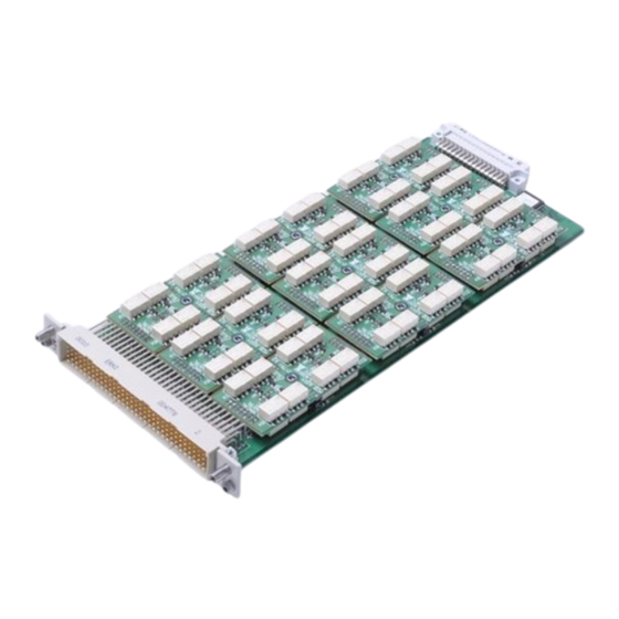
Chapter 1 SPECIFICATIONS The 1260-145A is a plug-in matrix switch module developed for the Introduction – Racal Instruments 1260-100 Adapt-a-Switch Carrier. This switch 1260-145A provides nine independent 4x4 matrices with a maximum switching (9 – 4x4’s) voltage of 125VAC @ 0.3A or 30 VDC @ 1A. -
Page 12: Electrical Specifications - 1260-145A
+5 VDC quiescent 0.1 A maximum each relay closure 0.02 A maximum Mean Time Between 33,784 Hours (MIL-HDBK-217FN2) Failures (MTBF) 50,714 Hours (Telcordia / Bellcore 6) Mean Time to Repair < 5 minutes (MTTR) Racal Instruments 2003 Module Specification 1-2... -
Page 13: Mechanical Specifications - 1260-145A
The largest contributor of thermal energy will therefore derive from the relay coils. Total power dissipation = [(144) * (0.100)] + [0.5] = 15W Racal Instruments 2003 Module Specification 1-3... -
Page 14: Introduction - 1260-145B (3 - 4X12'S)
1260-145A contributes a negligible amount of thermal load on a chassis. Introduction – The 1260-145B is a plug-in matrix switch module developed for the Racal Instruments 1260-100 Adapt-a-Switch Carrier. This switch 1260-145B provides three independent 4x12 matrices with a maximum (3 – 4x12’s) switching voltage of 125VAC @ 0.3A or 30 VDC @ 1A. -
Page 15: Electrical Specifications - 1260-145B
+5 VDC quiescent 0.1 A maximum each relay closure 0.02 A maximum Mean Time Between 33,773 Hours (MIL-HDBK-217FN2) Failures (MTBF) 50,687 Hours (Telcordia / Bellcore 6) Mean Time to Repair < 5 minutes (MTTR) Racal Instruments 2003 Module Specification 1-5... -
Page 16: Mechanical Specifications - 1260-145B
The largest contributor of thermal energy will therefore derive from the relay coils. Total power dissipation = [(144) * (0.100)] + [0.5] = 15W This is acceptable power dissipation for an individual plug-in Racal Instruments 2003 Module Specification 1-6... -
Page 17: Introduction - 1260-145C (2 - 4X16'S)
1260-145B contributes a negligible amount of thermal load on a chassis. Introduction – The 1260-145C is a plug-in matrix switch module developed for the Racal Instruments 1260-100 Adapt-a-Switch Carrier. This switch 1260-145C provides two independent 4x16 matrices with a maximum (2 – 4x16’s) switching voltage of 125VAC @ 0.3A or 30 VDC @ 1A. -
Page 18: Electrical Specifications - 1260-145C
+5 VDC quiescent 0.1 A maximum each relay closure 0.02 A maximum Mean Time Between 37,908 Hours (MIL-HDBK-217FN2) Failures (MTBF) 56,705 Hours (Telcordia / Bellcore 6) Mean Time to Repair < 5 minutes (MTTR) Racal Instruments 2003 Module Specification 1-8... -
Page 19: Mechanical Specifications - 1260-145C
The largest contributor of thermal energy will therefore derive from the relay coils. Total power dissipation = [(128) * (0.100)] + [0.5] = 13.3W This is acceptable power dissipation for an individual plug-in Racal Instruments 2003 Module Specification 1-9... -
Page 20: Introduction - 1260-145D (1 - 4X36)
Introduction – The 1260-145D is a plug-in matrix switch module developed for the Racal Instruments 1260-100 Adapt-a-Switch Carrier. This switch 1260-145D provides a 4x36 matrix with a maximum switching voltage of (1 – 4x36) 125VAC @ 0.3A or 30 VDC @ 1A. -
Page 21: Electrical Specifications - 1260-145D
+5 VDC quiescent 0.1 A maximum each relay closure 0.02 A maximum Mean Time Between 33,768 Hours (MIL-HDBK-217FN2) Failures (MTBF) 50,673 Hours (Telcordia / Bellcore 6) Mean Time to Repair < 5 minutes (MTTR) Racal Instruments 2003 Module Specification 1-11... -
Page 22: Mechanical Specifications - 1260-145D
The largest contributor of thermal energy will therefore derive from the relay coils. Total power dissipation = [(144) * (0.100)] + [0.5] = 15W This is acceptable power dissipation for an individual plug-in Racal Instruments 2003 Module Specification 1-12... -
Page 23: Introduction - 1260-145E (2 - 8X8'S)
1260-145D contributes a negligible amount of thermal load on a chassis. Introduction – The 1260-145E is a plug-in matrix switch module developed for the Racal Instruments 1260-100 Adapt-a-Switch Carrier. This switch 1260-145E provides two independent 8x8 matrices with a maximum switching (2 – 8x8’s) voltage of 125VAC @ 0.3A or 30 VDC @ 1A. -
Page 24: Electrical Specifications - 1260-145E
+5 VDC quiescent 0.1 A maximum each relay closure 0.02 A maximum Mean Time Between 37,904 Hours (MIL-HDBK-217FN2) Failures (MTBF) 56,694 Hours (Telcordia / Bellcore 6) Mean Time to Repair < 5 minutes (MTTR) Racal Instruments 2003 Module Specification 1-14... -
Page 25: Mechanical Specifications - 1260-145E
The largest contributor of thermal energy will therefore derive from the relay coils. Total power dissipation = [(128) * (0.100)] + [0.5] = 13.3W This is acceptable power dissipation for an individual plug-in Racal Instruments 2003 Module Specification 1-15... -
Page 26: Introduction - 1260-145F (1 - 8X16)
Introduction – The 1260-145F is a plug-in matrix switch module developed for the Racal Instruments 1260-100 Adapt-a-Switch Carrier. This switch 1260-145F provides a 8x16 matrix with a maximum switching voltage of (1 – 8x16) 125VAC @ 0.3A or 30 VDC @ 1A. -
Page 27: Electrical Specifications - 1260-145F
+5 VDC quiescent 0.1 A maximum each relay closure 0.02 A maximum Mean Time Between 37,899 Hours (MIL-HDBK-217FN2) Failures (MTBF) 56,682 Hours (Telcordia / Bellcore 6) Mean Time to Repair < 5 minutes (MTTR) Racal Instruments 2003 Module Specification 1-17... -
Page 28: Mechanical Specifications - 1260-145F
The largest contributor of thermal energy will therefore derive from the relay coils. Total power dissipation = [(128) * (0.100)] + [0.5] = 13.3W This is acceptable power dissipation for an individual plug-in Racal Instruments 2003 Module Specification 1-18... -
Page 29: Introduction - 1260-145G (1 - 12X12)
1260-145F contributes a negligible amount of thermal load on a chassis. Introduction – The 1260-145G is a plug-in matrix switch module developed for the Racal Instruments 1260-100 Adapt-a-Switch Carrier. This 1260-145G switch provides a 12x12 matrix with a maximum switching voltage (1 – 12x12) of 125VAC @ 0.3A or 30 VDC @ 1A. -
Page 30: Electrical Specifications - 1260-145G
+5 VDC quiescent 0.1 A maximum each relay closure 0.02 A maximum Mean Time Between 33,763 Hours (MIL-HDBK-217FN2) Failures (MTBF) 50,660 Hours (Telcordia / Bellcore 6) Mean Time to Repair < 5 minutes (MTTR) Racal Instruments 2003 Module Specification 1-20... -
Page 31: Mechanical Specifications - 1260-145G
The largest contributor of thermal energy will therefore derive from the relay coils. Total power dissipation = [(144) * (0.100)] + [0.5] = 15W This is acceptable power dissipation for an individual plug-in Racal Instruments 2003 Module Specification 1-21... - Page 32 For practical purposes, as the calculations can illustrate for normal operation, the 1260-145G contributes a negligible amount of thermal load on a chassis. Racal Instruments 2003 Module Specification 1-22...
-
Page 33: About Mtbf
160 Pin Conn. Kit with pins 407664 Cable Assy. 6ft, Sleeved 160 Pin Cable Assy, 6 Ft, 24 AWG 407408-001 Connector Bracket Bracket, Strain Relief 456673 Additional Manual 980824-145 This page intentionally left blank Racal Instruments 2003 Module Specification 1-23... - Page 34 1260-145 User Manual Racal Instruments 2003 Module Specification 1-24...
-
Page 35: Chapter 2
4. Have a qualified person check the instrument for safety before use. 1. Use the original packing material when returning the Reshipment switching module to Racal Instruments for servicing. The Instructions original shipping carton and the instrument’s plastic foam will provide the necessary support for safe reshipment. -
Page 36: Installation
See Figure 2-1 for pin numbering. Refer to Chapter 3 for channel to pin mapping. For a block diagram of the 1260-145 see Figure 2-2. DIN41612 Front Panel Connector Pinout Figure 2-1, Front-Panel Connector Pin Numbering Racal Instruments 2003 Installation Instructions 2-2... -
Page 37: Mating Connectors
P/N 990899. The 160-Pin Cable Assembly uses 24 AWG cable with crimp pins to mate with the 1260-145. The other cable end is un-terminated. Refer to Chapter 3 for channel-to-pin mapping information. Racal Instruments 2003 Installation Instructions 2-3... - Page 38 1260-145 User Manual This page was left intentionally blank. Racal Instruments 2003 Installation Instructions 2-4...
-
Page 39: Chapter 3
Front View – Module Addresses for 1 through 6 • 7 - 12 (open): When the switch is set to this position, the module addresses of the plug-ins in the 1260-100 Carrier are Racal Instruments 2003 Module Operation 3-1... -
Page 40: Operating Modes
0x804000A for example purposes and the 1260-145 occupies the module 0 slot, Figure 3-1 below provides a conceptual view of the message-based mode of operation for a read operation on port 1. Racal Instruments 2003 Module Operation 3-2... -
Page 41: Figure 3-1, Message-Based Mode Of Operation
1260-145. In this mode, direct port and control register operations are processed in less than 9 microseconds, not counting software overhead inherent in I/O libraries such as VISA. For further information about message-based vs. register-based Racal Instruments 2003 Module Operation 3-3... -
Page 42: Operating In Message-Based Mode
The following examples illustrate the use of the channel descriptors for the 1260-145: Closes relay 0 at module address CLOSE (@8(0)) Opens relay 1000 at module OPEN (@3(1000)) address 3 The message-based descriptors (MBC) provided in Figures 3-5 Racal Instruments 2003 Module Operation 3-4... -
Page 43: Reply To The Mod:list? Command
1260-145E 2-8X8 MATRIX MODULE 1260-145F 8X16 MATRIX MODULE 1260-145G 12X12 MATRIX MODULE So, for a 1260-145C whose <module address> is set to 8, the reply to this query would be: 8 : 1260-145C 2-4X16 MATRIX MODULE Racal Instruments 2003 Module Operation 3-5... -
Page 44: Operating The 1260-145 In Register-Based Mode
(Base A24 1260-145 Address) + offset = absolute address If slot 7 is assumed to be occupied by a 1260-145A card for Racal Instruments 2003 Module Operation 3-6... - Page 45 8-bit byte to a control register, while viIn8() is used to read a single 8-bit byte from the control register. The following code example shows the use of viOut8() to update the 1260-145 module. Racal Instruments 2003 Module Operation 3-7...
- Page 46 = Message-based channel descriptor for relay (also used as a general relay number) Off-bit = Register-based address offset (0x01-0x23) and bit location (0-7) for relay DIN41612 Front Panel Connector Pinout Figure 3-3, Numbering Nomenclature for all 1260-145 Variants Racal Instruments 2003 Module Operation 3-8...
-
Page 47: Figure 3-4, Message-Based Channel Descriptor To Physical Switch Orientation
= Row Number (00-15) RRCC Message Based = Column Number (00-07) Descriptor 1260-145G = Row Number (00-11) RRCC Message Based = Column Number (00-11) Descriptor Figure 3-4, Message-Based Channel Descriptor to Physical Switch Orientation Racal Instruments 2003 Module Operation 3-9... -
Page 48: Figure 3-5, 1260-145A Connector/Channel Organization
0x09-4 0x09-5 0x09-6 0x09-7 0000, 0001, 0002, 0003, 1000, 1001, 1002, 1003, 2000, 2001, 2002, 2003, 0x01-0 0x01-1 0x01-2 0x01-3 0x05-0 0x05-1 0x05-2 0x05-3 0x09-0 0x09-1 0x09-2 0x09-3 Figure 3-5, 1260-145A Connector/Channel Organization Racal Instruments 2003 Module Operation 3-10... -
Page 49: Figure 3-6, 1260-145B Connector/Channel Organization
0x09-4 0x09-5 0x09-6 0x09-7 00000, 00001, 00002, 00003, 00004, 00005, 00006, 00007, 00008, 00009, 00010, 00011, 0x01-0 0x01-1 0x01-2 0x01-3 0x05-0 0x05-1 0x05-2 0x05-3 0x09-0 0x09-1 0x09-2 0x09-3 Figure 3-6, 1260-145B Connector/Channel Organization Racal Instruments 2003 Module Operation 3-11... -
Page 50: Figure 3-7, 1260-145C Connector/Channel Organization
10100, 10101, 10102, 10103, 0x01-4 0x01-5 0x01-6 0x01-7 0x09-4 0x09-5 0x09-6 0x09-7 00000, 00001, 00002, 00003, 10000, 10001, 10002, 10003, 0x01-0 0x01-1 0x01-2 0x01-3 0x09-0 0x09-1 0x09-2 0x09-3 Figure 3-7, 1260-145C Connector/Channel Organization Racal Instruments 2003 Module Operation 3-12... -
Page 51: Figure 3-8, 1260-145D Connector/Channel Organization
0x19-4 0x19-5 0x19-6 0x19-7 0000, 0001, 0002, 0003, 1200, 1201, 1202, 1203, 2400, 2401, 2402, 2403, 0x01-0 0x01-1 0x01-2 0x01-3 0x0d-0 0x0d-1 0x0d-2 0x0d-3 0x19-0 0x19-1 0x19-2 0x19-3 Figure 3-8, 1260-145D Connector/Channel Organization Racal Instruments 2003 Module Operation 3-13... -
Page 52: Figure 3-9, 1260-145E Connector/Channel Organization
10104, 10105, 10106, 10107, 0x09-4 0x09-5 0x09-6 0x09-7 0x21-4 0x21-5 0x21-6 0x21-7 10000, 10001, 10002, 10003, 10004, 10005, 10006, 10007, 0x09-0 0x09-1 0x09-2 0x09-3 0x21-0 0x21-1 0x21-2 0x21-3 Figure 3-9, 1260-145E Connector/Channel Organization Racal Instruments 2003 Module Operation 3-14... -
Page 53: Figure 3-10, 1260-145F Connector/Channel Organization
0104, 0105, 0106, 0107, 0x01-4 0x01-5 0x01-6 0x01-7 0x05-4 0x05-5 0x05-6 0x05-7 0000, 0001, 0002, 0003, 0004, 0005, 0006, 0007, 0x01-0 0x01-1 0x01-2 0x01-3 0x05-0 0x05-1 0x05-2 0x05-3 Figure 3-10, 1260-145F Connector/Channel Organization Racal Instruments 2003 Module Operation 3-15... -
Page 54: Figure 3-11, 1260-145G Connector/Channel Organization
0x09-4 0x09-5 0x09-6 0x09-7 0000, 0001, 0002, 0003, 0004, 0005, 0006, 0007, 0008, 0009, 0010, 0011, 0x01-0 0x01-1 0x01-2 0x01-3 0x05-0 0x05-1 0x05-2 0x05-3 0x09-0 0x09-1 0x09-2 0x09-3 Figure 3-11, 1260-145G Connector/Channel Organization Racal Instruments 2003 Module Operation 3-16... -
Page 55: 1260-145 Example Code
/* error handling code goes here */ /* form the offset for control register 0 */ /* note that the base A24 Address for the 1260-01T */ /* is already accounted for by VISA calls viIn8() and */ Racal Instruments 2003 Module Operation 3-17... - Page 56 = viOut8 (vi, VI_A24_SPACE, offset, DATA_ITEM); if (error < 0) return( error ); /* close the VISA session */ error = viClose( hdl1260 ); if (error < 0) { /* error handling code goes here */ Racal Instruments 2003 Module Operation 3-18...
-
Page 57: Chapter 4
1260-145 User Manual Chapter 4 OPTIONAL ASSEMBLIES 407664 Connector Kit, 160 Pin Crimp ..............4-3 407408-001 Cable Assy, 160 Pin, 6 ft, 24AWG............4-4 Racal Instruments 2003 Optional Harness Assemblies 4-1... - Page 58 1260-145 User Manual This page was left intentionally blank. Racal Instruments 2003 Optional Harness Assemblies 4-2...
- Page 59 1260-145 User Manual RACAL INSTRUMENTS, INC. Assembly 407664 Connector kit, 160 Pin, Crimp Rev Date 7/30/98 Revision A Component Description Qty Reqd. 602258-116 CON-CAB-RCP160C,100S -E EA 1.000 602258-900 TRMCRP-SNP-U-F26-20G -E EA 170.000 Racal Instruments 2003 Optional Harness Assemblies 4-3...
- Page 60 1260-145 User Manual Racal Instruments 2003 Optional Harness Assemblies 4-4...
-
Page 61: Chapter 5
1260-145 User Manual Chapter 5 PRODUCT SUPPORT Racal Instruments has a complete Service and Parts Department. Product Support If you need technical assistance or should it be necessary to return your product for repair or calibration, call 1-800-722-3262. If parts are required to repair the product at your facility, call 1-949-859- 8999 and ask for the Parts Department. -
Page 62: Support Offices
Via Milazzo 25, 20092 Cinisello B, Milan, Italy Tel: +39 (0)2 6123 901; Fax: +39 (0)2 6129 3606 Technologie Park, Friedrich Ebert Strasse, 51429 Bergisch Gladbach, Germany Tel: +49 (0) 2204 844200; Fax: +49 (0) 2204 844219 Racal Instruments 2003 Product Support 5-2... -
Page 63: Repair And Calibration Request Form
3. Please give any additional information you feel would be beneficial in facilitating a faster repair time (i.e., modifications, etc.) 4. Is calibration data required? Yes No (please circle one) Call before shipping Ship instruments to nearest support office. Note: We do not accept “collect” shipments. Racal Instruments 2003 Product Support 5-3...
Need help?
Do you have a question about the 1260 VXI and is the answer not in the manual?
Questions and answers