Table of Contents
Advertisement
Quick Links
1260 VXI X-Series SWITCHING CARD
1x8 MULTIPLEXER PLUG-IN
MODEL 1260-X138
Tel: (800) 722-2528, (949) 859-8999; Fax: (949) 859-7139
5730 Northwest Parkway Suite 700, San Antonio, TX 78249
Tel: +33 (0)1 39 23 22 22; Fax: +33 (0)1 39 23 22 25
29-31 Cobham Road, Wimborne, Dorset BH21 7PF, United Kingdom
Tel: +44 (0) 1202 872800; Fax: +44 (0) 1202 870810
Racal Instruments Group Limited, Technologie Park, D-51429 Bergisch Gladbach, Germany
PUBLICATION DATE: December 21, 2005
Copyright 2005 by Racal Instruments, Inc. Printed in the United States of America. All rights reserved.
This book or parts thereof may not be reproduced in any form without written permission of the publisher.
PUBLICATION NO. 980914-X138
RACAL INSTRUMENTS
United States
(Corporate Headquarters and Service Center)
4 Goodyear Street, Irvine, CA 92618
Tel: (210) 699-6799; Fax: (210) 699-8857
Europe
(European Headquarters and Service Center)
18 Avenue Dutartre, 78150 LeChesnay, France
Via Milazzo 25, 20092 Cinisello B, Milan, Italy
Tel: +39 (0)2 6123 901; Fax: +39 (0)2 6129 3606
Tel: +49 2204 844205; Fax: +49 2204 844219
info@racalinstruments.com
sales@racalinstruments.com
helpdesk@racalinstruments.com
http://www.racalinstruments.com
info@racalinstruments.de
www.racalinstruments.de
Advertisement
Table of Contents

Subscribe to Our Youtube Channel
Related Manuals for Racal Instruments 1260-100X X Series


Summary of Contents for Racal Instruments 1260-100X X Series
- Page 1 PUBLICATION DATE: December 21, 2005 Copyright 2005 by Racal Instruments, Inc. Printed in the United States of America. All rights reserved. This book or parts thereof may not be reproduced in any form without written permission of the publisher.
- Page 2 THANK YOU FOR PURCHASING THIS RACAL INSTRUMENTS PRODUCT. For this product, or any other Racal Instruments product that incorporates software drivers, you may access our web site to verify and/or download the latest driver versions. The web address for driver downloads is: http://www.racalinstruments.com/downloads...
- Page 3 Authorization is required from Racal Instruments before you send us your product for service or calibration. Call your nearest Racal Instruments support facility. A list is located on the last page of this manual. If you are unsure where to call, contact Racal Instruments, Inc. Customer Support Department in Irvine, California, USA at 1-800-722-3262 or 1-949-859-8999 or via fax at 1-949-859-7139.
- Page 4 FOR YOUR SAFETY Before undertaking any troubleshooting, maintenance or exploratory procedure, read carefully the WARNINGS and CAUTION notices. This equipment contains voltage hazardous to human life and safety, and is capable of inflicting personal injury. If this instrument is to be powered from the AC line (mains) through an autotransformer, ensure the common connector is connected to the neutral (earth pole) of the power supply.
-
Page 5: Table Of Contents
1260-X138 User Manual Table of Contents Chapter 1 ..........................1-1 SPECIFICATIONS .......................... 1-1 Introduction..........................1-1 Specifications ..........................1-3 Ordering Information ........................1-6 Chapter 2 ..........................2-1 INSTALLATION INSTRUCTIONS....................2-1 Unpacking and Inspection ......................2-1 Reshipment Instructions......................2-1 Installation ........................... 2-2 Module Configuration ........................ - Page 6 1260-X138 User Manual Channel Descriptors For The 1260-X138 .................3-4 Reply To The MOD:LIST? Command..................3-5 Operating The 1260-X138 in Register-Based Mode ..............3-5 Configuring Larger Multiplexers ....................3-8 Creating Very Large Multiplexers With the Analog Bus ...............3-9 1260-X138 Example Code......................3-11 Chapter 4 ..........................4-1 PRODUCT SUPPORT........................4-1 Product Support ...........................4-1 Reshipment Instructions.......................4-1...
- Page 7 1260-X138 User Manual List of Figures Figure 1-1 The 1260-X138......................1-2 Figure 2-1 Single Multiplexer Example (Channels 70 through 77) ..........2-3 Figure 2-2 1260-X138 Block Diagram 1x8 High Side Groups 0, 1, 2, 3, 4, and 5 ......2-6 Figure 2-3 1260-X138 1x8 Relay Groups 6 and 7 .................
- Page 8 1260-X138 User Manual This page was left intentionally blank.
-
Page 9: Chapter 1
Data-driven embedded descriptor, allowing immediate use with any Option-01T switch controller, regardless of firmware revision level. • Capability of combining multiple multiplexers on-board to form large multiplexers. • Analog bus for combining multiple 1260-X138 plug-ins, to form very large multiplexers. Racal Instruments © 2005 Specifications 1-1... -
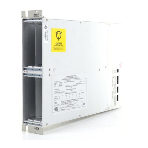
Page 10: Figure 1-1 The 1260-X138
1260-X138 User Manual Figure 1-1 The 1260-X138 Racal Instruments © 2005 Specifications 1-2... -
Page 11: Specifications
>64dB @ 1MHz >45dB @10 MHz Analog Channels: >80dB @ 1MHz >45dB @ 10MHz Noise Floor (MUX or Analog Channels): < -100dB from DC to 10MHz Switching Voltage: 250VAC, Max 220VDC, Max 300V (Pollution Class 1) Racal Instruments © 2005 Specifications 1-3... - Page 12 Maximum Power Dissipation: 60W below 10,000 feet* Cooling (25% Relays energized operating at full rated current): 2.00 Liters/sec @ 0.15 mmH Shock, Functional: 30g, 11 ms, ½ sine wave Vibration, Non-operating: 0.013 in. P-P, 5-55 Hz Racal Instruments © 2005 Specifications 1-4...
- Page 13 With relays 159,021 hours at 25°C With relays 142,422 hours at 30°C Safety Standard: EN61010-1 Pollution Class 2 Impulse Withstand 1000V *Operation at between 10,000 feet and 15,000 feet requires de- rating of maximum overall power dissipation to 49W Racal Instruments © 2005 Specifications 1-5...
-
Page 14: Ordering Information
1260-X138 X-series Switch Switch Module, 8 (1X8) 2 Wire MUX, 2 A 408010 Module Consists of: P/N 980914-X138 Manual 160-pin Mating Connector 160 Pin Conn. Kit with pins 407664 Additional Manual 1260-X138 Manual 980914-X138 Racal Instruments © 2005 Specifications 1-6... -
Page 15: Chapter 2
Open the package at an ESD-safe work station. 1. Use the original packing material when returning the Reshipment switching module to Racal Instruments for servicing. The Instructions original shipping carton and the instrument’s plastic foam will provide the necessary support for safe reshipment. -
Page 16: Installation
Eight 1x8s, four 1x16s, two 1x32s, or one 1x64. In addition Multiplexer groups 0, 1, 2 and groups 3, 4, 5 can be configured to form three 2x8s, two 2x16s, or one 2x24. Racal Instruments © 2005 Installation Instructions 2-2... -
Page 17: Figure 2-1 Single Multiplexer Example (Channels 70 Through 77)
High Channel 73 Input High Mux 7 Common Output High Channel 74 Input High Channel 75Input High Channel 76 Input High Channel 77 Input Figure 2-1 Single Multiplexer Example (Channels 70 through 77) Racal Instruments © 2005 Installation Instructions 2-3... -
Page 18: Table 2-1 Relay Groups
Table 2-2 lists the relays responsible for forming the 2x8 mode. For example, by activating K31-K38, Group 0 and Group 3 can form a 2x8 2-wire multiplexer by switching common input of MUX Group 0 (E3, E2) and MUX Group 3 (E7, E6). Racal Instruments © 2005 Installation Instructions 2-4... -
Page 19: Table 2-2 2X8 Formation Relays
MUX5 CH30- _COM CH37 CH41- CH47 CH51- CH57 3, 4, 5 * 2x24 K85 – K108, K79, K80 MUX5 CH00- Energized K31- K54 _COM CH07 CH10- CH17 CH20- *Group 0, 1, CH27 Disconnected Racal Instruments © 2005 Installation Instructions 2-5... - Page 20 1260-X138 User Manual Figure 2-2 1260-X138 Block Diagram 1x8 High Side Groups 0, 1, 2, 3, 4, and 5 Racal Instruments © 2005 Installation Instructions 2-6...
- Page 21 Figure 2-3 shows two independent 1x8 2-wire mode multiplexers Groups 6 and 7. These two groups can be connected to the six groups shown in Figure 2-2. Figure 2-3 1260-X138 1x8 Relay Groups 6 and 7 Racal Instruments © 2005 Installation Instructions 2-7...
-
Page 22: Configuration Relays
Group 2, Group 5, Group 6, and Group 7, respectively to analog bus pairs ABUS0, ABUS1, ABUS2, and ABUS3, respectively. For details on using the analog bus, refer to the section “Creating Very Large Multiplexers with the Analog Bus” in Chapter 3. Racal Instruments © 2005 Installation Instructions 2-8... -
Page 23: Figure 2-4 Front-Panel Connector Pin Numbering
1260-X138 User Manual Figure 2-4 Front-Panel Connector Pin Numbering a b c d e Racal Instruments © 2005 Installation Instructions 2-9... -
Page 24: Front Panel Connector
Figure 2-4 for the physical pin arrangement. Table 2-3 shows the mapping of channel numbers to connector pins. For information about mating connectors and accessories, see the “Mating Connectors” section at the end of this chapter. Racal Instruments © 2005 Installation Instructions 2-10... -
Page 25: Connector Pin Assignments
Table 2-5 provides the pin assignments for the front panel Connector Pin connector. Assignments Table 2-5 1260-X138 Front-Panel Connections for J200 Channel High Mux 0 Common Mux 1 Common Mux 2 Common Mux 3 Common Racal Instruments © 2005 Installation Instructions 2-11... - Page 26 1260-X138 User Manual Channel High Mux 4 Common Mux 5 Common Mux 6 Common Mux 7 Common Racal Instruments © 2005 Installation Instructions 2-12...
- Page 27 CHASSIS GND pins shall be used if AFGND is used as the primary shielding and is tied to the customer’s ground. *Pins E1, E5, E9, E13, E17, E21, E25, and E28 are reserved for future use. **CHASSIS GND pins are connected to the AFGND via a 1500pf 2KV capacitor. Racal Instruments © 2005 Installation Instructions 2-13...
-
Page 28: Mating Connectors
170 crimp pins. After crimping, the pins snap into the connector housing, providing positive retention. P/N 991033: ERNI Tool Kit. This kit includes the crimp tool and extractor. P/N 990898: Insertion Hand Tool. P/N 990899: Extraction Tool. Racal Instruments © 2005 Installation Instructions 2-14... -
Page 29: Chapter 3
6. The module with address 1 is in the left slot of the top row. The plug-ins are addressed in the following pattern: Figure 3-1 Front View – Module Addresses for 1 through 6 Racal Instruments © 2005 Module Operation 3-1... -
Page 30: Operating Modes
A conceptual view of the message-based mode of operation is shown in Figure 3-3 below. It sends “1” to bit 5 while maintaining the other bits to “0” thus closing only channel 5 and keeping other channels open. Racal Instruments © 2005 Module Operation 3-2... -
Page 31: Figure 3-3 Message-Based Mode Of Operation
1260-01T. In addition, some features, such as the SCAN list, are available only in the message-based mode of operation. The register-based mode provides faster control of relay channels. Racal Instruments © 2005 Module Operation 3-3... -
Page 32: Operating In Message-Based Mode
, . . ., <chanN> )) A range of channels may be specified using the following channel descriptor syntax: @ <module address> ( <first channel> : <last channel> )) The following examples illustrate the use of the channel Racal Instruments © 2005 Module Operation 3-4... -
Page 33: Reply To The Mod:list? Command
The A24 Address Offset is placed into the “Offset Register” of the 1260-01T by the Resource Manager. 2. The <module address> of the 1260-X138 module. This is a value in the range from 1 and 12 inclusive. Racal Instruments © 2005 Module Operation 3-5... - Page 34 K7 to K14. 205C03 Control Register Group 1, controls channels K15 to K22. 205C05 Control Register Group 2, controls channels K23 to K30. Table 3-2 shows the channel assignments for each control register. Racal Instruments © 2005 Module Operation 3-6...
-
Page 35: Table 3-1 Control Register Channel Assignments
In other words, the eight-bit value read back is the one’s complement of the value written. If you want to change the state of a single relay without affecting the present state of the other relays controlled by the control register, you must: Racal Instruments © 2005 Module Operation 3-7... -
Page 36: Configuring Larger Multiplexers
As a configuration example, suppose you require two 1x16 multiplexes and one 1x24 multiplexer. You may form these multiplexers from a 1260-X138 by configuring it as follows: 1. Combine muxes 0 and 1 to form a 1x16 multiplexer. To do Racal Instruments © 2005 Module Operation 3-8... -
Page 37: Creating Very Large Multiplexers With The Analog Bus
Close the “ABUS 3” relay K112 on the first plug-in. Referring to Table 3-1, we see that this relay is controlled by bit 3 of control register 0x021. Set the bit to 1 to close the relay. Racal Instruments © 2005 Module Operation 3-9... - Page 38 1x128 matrix. Note that, in the above example, paths ABUS 0, ABUS 1, ABUS 2 are unused. If desired, you may use these independent paths to connect additional groups of plug-ins together. Racal Instruments © 2005 Module Operation 3-10...
-
Page 39: 1260-X138 Example Code
/* error handling code goes here */ /* form the offset for control register 0 */ /* note that the base A24 Address for the 1260-01T */ /* is already accounted for by VISA calls viIn8() and */ Racal Instruments © 2005 Module Operation 3-11... - Page 40 /* leave bit 0 clear to open channel 47 */ creg_val &= ~ (0x01); /* write the updated control register value */ error = viOut8 (hdl1260, VI_A24_SPACE, creg2_addr, creg_val); if (error < 0) { /* error handling code goes here */ Racal Instruments © 2005 Module Operation 3-12...
- Page 41 1260-X138 User Manual /* close the VISA session */ error = viClose( hdl1260 ); if (error < 0) { /* error handling code goes here */ Racal Instruments © 2005 Module Operation 3-13...
- Page 42 1260-X138 User Manual This page was left intentionally blank. Racal Instruments © 2005 Module Operation 3-14...
-
Page 43: Chapter 4
1260-X138 User Manual Chapter 4 PRODUCT SUPPORT Racal Instruments has a complete Service and Parts Department. Product Support If you need technical assistance or should it be necessary to return your product for repair or calibration, call 1-800-722-3262. If parts are required to repair the product at your facility, call 1-949-859-8999 and ask for the Parts Department. -
Page 44: Support Offices
Via Milazzo 25, 20092 Cinisello B, Milan, Italy Tel: +39 (0)2 6123 901; Fax: +39 (0)2 6129 3606 Technologie Park, Friedrich Ebert Strasse, 51429 Bergisch Gladbach, Germany Tel: +49 (0) 2204 844200; Fax: +49 (0) 2204 844219 Racal Instruments © 2005 Product Support 4-2... - Page 45 3. Please give any additional information you feel would be beneficial in facilitating a faster repair time (i.e., modifications, etc.) 4. Is calibration data required? Yes No (please circle one) Call before shipping Ship instruments to nearest support office. Note: We do not accept “collect” shipments. Racal Instruments © 2005 Product Support 4-3...
Need help?
Do you have a question about the 1260-100X X Series and is the answer not in the manual?
Questions and answers