PITH & STEM DropTop Instructions Manual
Hide thumbs
Also See for DropTop:
- Instructions manual (33 pages) ,
- Assembly/installation instructions (38 pages) ,
- Assembly/installation instructions (38 pages)

Related Manuals for PITH & STEM DropTop


Summary of Contents for PITH & STEM DropTop
- Page 1 DropTop.™ Single Light Instructions www.pithandstem.com © 2023 Pith & Stem ltd. All rights reserved. Page: 1...
- Page 2 DropTop.™ Single Light Instructions. Fixings Packs Brick/Concrete Wall Plasterboard Wall Fixings Fixings Tools *included *Not included *Not included For a Plasterboard Wall 25mm hole saw or a 25mm Spade bit Page: 2...
- Page 3 DropTop.™ Single Light Parts Page: 3...
- Page 4 DropTop.™ Single Light dimensions. 1 4 c Exterior dimensions when Closed: Height: 67cm Width: 87cm Depth: 15.8cm 1 0 c Worktop Dimensions: Width: 87cm Depth: 55cm The Single Light supports up 54cm to 50kg in weight 1 0 c Weight - 20kg...
- Page 5 DropTop.™Single Light Monitor space dimensions The Single Light is designed to house a 24-inch or a 29-inch 1 0 c Ultrawide monitor. Available Monitor Space dimensions: Height: 35cm 3 7 c Width: 75cm Depth: Please see note below* Please note that the...
- Page 6 Monitor Mounts. Your DropTop™ Light will include one of the following monitor brackets, depending on your order. Extendable Arm Mount Slim Mount Depth: 5cm Depth: 1.3cm The recommended The recommended maximum depth maximum depth for your monitor is 8cm for your monitor is 5cm Tilt Mount Depth: 3.3cm...
- Page 7 DropTop.™Single Light Wall Plate dimensions. 2 cm 3 . 7 c 10.4cm Page: 7...
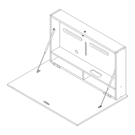
- Page 8 DropTop.™Single Light Cable Management The Single Light is designed with a back recess depth of 1.6cm. This allows for any cables to be fed tidily behind the DropTop 1 . 6 It is recommended to feed the monitor's power cable through round cable management 5 .
- Page 9 DropTop.™Single Light Assembly Fixings Pack #1 Fixings Pack #2 Page: 9 Page: 9...
- Page 10 Front Front View Back View Fixings Pack #3 Fixings Pack #1 At this step, make sure to position Part B at the front view instead of the back, as shown above. Page: 10...
- Page 11 Fixings Pack #2 Fixings Pack #3 Fixings Pack #1 Page: 11...
- Page 12 Fixings Pack #2 Fixings Pack #4 Page: 12...
- Page 13 Fixings Pack #2 Fixings Pack #3 Fixings Pack #2 Fixings Pack #5 Page: 13...
- Page 14 Fixings Pack #7 Cable management grommet. Insert the two thin metal disks into the black oval-shaped ring. Fixings Pack #8 Fixings Pack #7 Page: 14...
- Page 15 After your DropTop is mounted, the speed of Matching colour cover cap stickers have the soft opening feature can be adjusted. been provided with your DropTop.™ Locate the ridged surface at the end of each Apply the cover caps over any exposed stay to make adjustments.
- Page 16 To install your monitor on a Slim or Tilt mount. Your DropTop.™ comes with either a Slim Monitor Mount or a Tilt Monitor Mount, depending on your chosen configuration. Monitor Back View Slim Monitor Mount Tilt Monitor Mount Attach the screen mount to the monitor using the screws that were provided.
- Page 17 Front View Back View Insert your monitor into the desk and fit the monitor bolts into the screen mount loosely. Adjust the screen mount to the desired height, then tighten the bolts. Page: 17...
- Page 18 To install your monitor on an Extendable Arm Mount 4 x M4 Bolt-f This way up. This way up. 2x VESA Plate-b 2x Wall Plate & Articulating Arms-A Carefully place your monitors face down on a clean, flat surface. Attach the VESA Plate-b to the back of your monitor using the M4 Bolts-f 2 x M4 Bolt - d 2 x M6 Bolt 4x M4 Bolt - f...
- Page 19 Fully extend the articulating arms out. Wall Plate & Articulating Arms-A Back View 2 x M6 Bolt Attach the Wall Plate & Articulating Arms-A to the VESA slot on the back of the DropTop, using the 2 x M6 bolts provided. Page: 19...
- Page 20 2 x M4 Bolt - d Secure the VESA Plate-b to the articulating arm using the 2x M4 Bolt-d provided. Use the wrench provided to adjust the tilting angle of the Hook the VESA Plate-b to the Socket on VESA Plate-b. the fully extended arms.
- Page 21 Back View To adjust the height of the mount along the VESA slot, slightly loosen the M6 bolts on the back, then reposition the mount to the desired height and The mount brackets should be positioned as tighten the bolts again. indicated in the diagram to ensure proper and mounting of the monitors.
- Page 22 49cm Your preferred desk height Floor Your DropTop.™ desk can be installed at any height that best suits your needs and preferences. The height to install the wall plate should be measured from the top of the desired desk height Depending on your preferred sitting position, to the top of the recessed area of the wall plate.
- Page 23 Installing on a brick and concrete wall. WALL 49cm Use the wall plate as a guide and mark the position of the fixing holes with a pencil. The height to install the wall plate should be measured from the top of the desired desk Drill 6 x 8mm sized holes.
- Page 24 WALL WALL Fixings Pack To safely mount the desk, ensure that the DropTop.™ is locked before lifting it onto the wall plate. The DropTop.™ should fit snugly in the recess of the wall plate. Page: 24...
- Page 25 To safely remove the desk from the wall, mounted on the wall, use a long thin tool make sure that the DropTop is locked or pencil to mark the position of the mirror before lifting it off the wall plate.
- Page 26 WALL Fixings Pack To safely mount the desk, ensure that the DropTop.™ is locked before lifting it onto the Drill the 2 x 6mm holes previously marked wall plate. The DropTop.™ should fit snugly in for the mirror screws and insert the wall the recess of the wall plate.
- Page 27 WALL Fixings Pack #8 Screw the mirror screw caps. Page: 27...
- Page 28 Installing on Plasterboard/Drywall. *Not included Recommended tools 25mm hole saw or a 25mm Spade bit WALL 49cm Use the wall plate as a guide and mark the position of the fixing holes with a pencil. Using a hole saw, cut 3 holes of 25mm diameter centred on the top row of your wall plate pencil The height to install the wall plate should be markings for the Geefix.
- Page 29 GeeFix Fixings Assemble your GeeFix wall anchor system by threading the supplied pullcord through the round wall plug, the curved back plate, and back through the wall plug. While holding onto the pullcord, feed the curved back plate into the hole and centre WALL on the 1″...
- Page 30 Front View To safely mount the desk, ensure that the DropTop.™ is locked before lifting it onto While the DropTop.™ is on the wall, use a the wall plate. The DropTop.™ should fit long thin tool or pencil and mark the snugly in the recess of the wall plate.
- Page 31 Fixings Pack To safely remove the desk from the wall, Drill the 2 x 6mm holes previously marked make sure that the DropTop is locked for the mirror screws and insert the wall before lifting it off the wall plate.
- Page 32 Fixings Pack #8 Screw the mirror screw caps. To safely mount the desk, ensure that the DropTop.™ is locked before lifting it onto the wall plate. The DropTop.™ should fit snugly in the recess of the wall plate. Page: 32...
- Page 33 DropTop.™ Single Light Instructions www.pithandstem.com © 2023 Pith & Stem ltd. All rights reserved. Page: 33 Page: 33...
Need help?
Do you have a question about the DropTop and is the answer not in the manual?
Questions and answers