PITH & STEM DropTop Max Light Assembly/Installation Instructions
Hide thumbs
Also See for DropTop Max Light:
- Instructions manual (33 pages) ,
- Instructions manual (33 pages) ,
- Assembly/installation instructions (38 pages)

Subscribe to Our Youtube Channel
Related Manuals for PITH & STEM DropTop Max Light


Summary of Contents for PITH & STEM DropTop Max Light
- Page 1 DropTop™Max Light Assembly & Installation Instructions Page: 1 © 2024 Pith & Stem Ltd. All rights reserved.
-
Page 2: Before You Begin
DropTop™Max Light Assembly & Installation Guidelines Please read and follow these instructions carefully to ensure the correct assembly and installation of your DropTop™ wall-mounted desk. Failure to adhere to the instructions may result in product damage, personal injury, or voiding of the product warranty. Before You Begin: •... - Page 3 DropTop™ Max Light Fixings Pack x7 +1 Extra +1 Extra + 2 Extra +1 Extra Brick/Concrete Wall Plasterboard Wall Fixings Fixings Tools *Not included *included *Not included For a Plasterboard Wall 25mm hole saw or a 25mm Spade bit Page: 3...
- Page 4 DropTop™ Max Light Parts Page: 4...
- Page 5 DropTop™ Max Light dimensions 1 4 c Exterior dimensions when Closed: Height: 72cm 9 5 . Width: 100cm Depth: 15.8cm 1 0 c Worktop Dimensions: Width: 100cm Depth: 59.7cm 4 5 c The Max Light supports up to 59cm 50kg in weight 1 0 c Weight - 25kg To safely mount your...
- Page 6 DropTop™ Max Light Monitor space dimensions The Max Light is designed to house a 27-inch or a 34-inch Ultrawide monitor. Available Monitor Space dimensions: Height: 42cm Width: 87.5cm 1 0 c Depth: Please see note below* 8 7 . Please note that the available 5 c m monitor space depth will vary based on your chosen Monitor...
- Page 7 Monitor Mounts. Your DropTop™ Light will include one of the following monitor brackets, depending on your order configuration. Extendable Arm Mount Slim Mount Depth: 5cm Depth: 1.3cm The recommended The recommended maximum depth maximum depth for your monitor is 8cm for your monitor is 5cm Tilt Mount Depth: 3.3cm...
- Page 8 DropTop™ Max Light Wall Plate dimensions. 2 cm 3 . 7 c m 5 0 c 10.4cm Page: 8...
- Page 9 DropTop™ Max Light Cable Management The Max Light is designed with a back recess depth of 1.6cm. This allows for any cables to be fed tidily behind the DropTop 1 . 6 It is recommended to feed the monitor's power cable through round cable management grommet 5 .
- Page 10 DropTop™ Max Light Assembly Fixings Pack #2 Correct. Incorrect. Fixings Pack #3 Fixings Pack #1 Ensure that part F is correctly oriented before assembly, as shown. Page: 10...
- Page 11 Front View Back View Fixings Pack #3 Fixings Pack #1 At this step, Ensure Part B is facing frontwards, as illustrated, not backwards at this stage Page: 11...
- Page 12 Fixings Pack #2 Page: 12 Page: 12...
-
Page 13: Back View
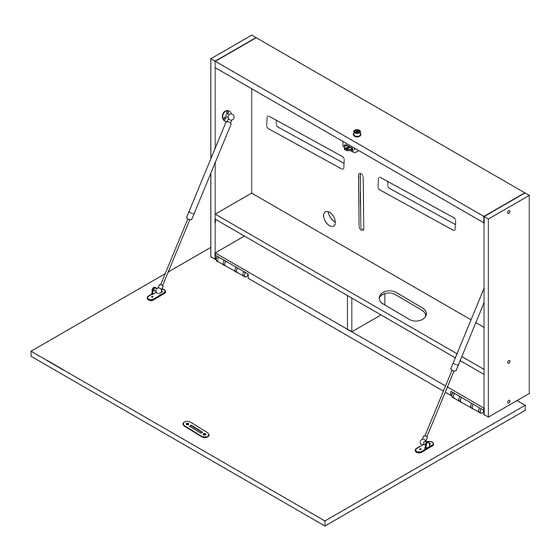
Fixings Pack #3 Fixings Pack #2 Fixings Pack #2 Fixings Pack #5 Back View Page: 13 Page: 13... - Page 14 Fixings Pack #7 Fixings Pack #7 Fixings Pack #7 Fixings Pack #6 Fixings Pack #7 Fully extend the soft opening stays by pulling on each end. Spheres must point inwards Page: 14...
- Page 15 Fixings Pack #4 Fixings Pack #4 Page: 15...
- Page 16 Oval Cable management Round Cable management grommet. grommet. 1. Push out the 1. Place the two central section of slender metal the circular cable discs into the grommet. You'll use it later. black oval ring, aligning them correctly. 2. Fit the outer ring of the cable grommet into part B's circular recess,...
- Page 17 Matching colour cover cap stickers have been provided with your DropTop™ Place the provided colour-matched cover cap stickers over any exposed screws for a clean finish. Page: 17 Page: 17...
- Page 18 To install your monitor on a Slim or Tilt mount. Your DropTop™ comes with either a Slim Monitor Mount or a Tilt Monitor Mount, depending on your chosen configuration. This way up. This way up. Slim Monitor Mount Tilt Monitor Mount Fix the VESA plate to the monitor with the supplied screws.
- Page 19 Attach your selected cable to the monitor and pass it through the oval- shaped cable grommet on panel E. Feed the power cable through the cable management cutout. Place the monitor face down on the worktop. After cabling, reattach the central Feed the power cable through the round cable section to the round cable grommet.
- Page 20 Back View Secure the monitor from the front. At the back, insert and lightly screw the bolts to keep it in Place your monitor into the DropTop™ monitor position. Fine-tune the height as needed, then space, ensuring cables are properly routed fully tighten the bolts to firmly secure the through.
- Page 21 To install your monitor on an Extendable Arm Mount f- M4 ×12Bolt a -Wall Plate & b-VESA Plate(1) c-Wrench(1) Articulating Arms(1) This way up. This way up. Flat Back Monitor. d-Bolt(2) f- M4 ×12Bolt l-Cable Tie(3) Attach the VESA Plat-b to your monitors using the provided screws.
- Page 22 Front View Fully extend the articulating arms out. Wall Plate & Articulating Arms-A Back View 2 x M6 Bolt Attach the Wall Plate & Articulating Arms-A to the VESA slot on the back of the DropTop, using the 2 x M6 bolts provided. Page: 22...
- Page 23 Attach your selected cable to the monitor and pass it through the oval- shaped cable grommet on panel E. Feed the power cable through the cable management cutout. Place the monitor face down on the worktop. After cabling, reattach the central Feed the power cable through the round cable section to the round cable grommet.
- Page 24 2 x M4 Bolt - Secure the VESA Plate-b to the articulating arm using the 2x M4 Bolt- d provided. Use the wrench provided to adjust the tilting angle of the Hook the VESA Plate-b to the Socket on VESA Plate-b. the fully extended arms.
- Page 25 The mount brackets should be positioned as Place your monitor into the DropTop™ monitor indicated in the diagram to ensure proper and space, ensuring cables are properly routed mounting of the monitors. through. Page: 25...
- Page 26 Back View While securing the monitor from the front, slightly loosen the screws at the back and adjust the height as needed. Once the desired height is achieved, fully tighten the bolts to firmly secure the monitor. Page: 26 Page: 26...
-
Page 27: Mounting The Wall Plate
Mounting the Wall plate. DropTop™ Max Light Wall plate height Wall plate Height 54cm Worktop Height 54cm Your preferred desk height Floor Your DropTop™ desk can be installed at any height that best suits your needs and The height to install the wall plate should be preferences. - Page 28 Installing on a brick and concrete wall. WALL 54cm Use the wall plate as a guide and mark the position of the fixing holes with a pencil. The height to install the wall plate should be measured from the top of the desired desk Drill 6 x 8mm sized holes at a depth of 90mm (9cm).
- Page 29 WALL WALL Fixings Pack To safely mount the desk, ensure that the DropTop™ is locked before lifting it onto the wall plate. The DropTop™ should fit snugly in the recess of the wall plate. Page: 29...
- Page 30 The securing screws in Fixings pack #8 will ensure that your desk does not accidentally come off its wall mount. WALL WALL Front View After the DropTop™ desk has been To safely remove the desk from the wall, To safely remove the desk from the wall, mounted on the wall, use a long thin tool make sure that the DropTop™...
- Page 31 WALL WALL Fixings Pack To safely mount the desk, ensure that the DropTop™ is locked before lifting it onto the Drill the 2 x 6mm holes previously marked wall plate. The DropTop™ should fit snugly in for the mirror screws and insert the wall the recess of the wall plate.
- Page 32 WALL Fixings Pack #8 Screw the mirror screw caps. Page: 32 Page: 32...
- Page 33 Installing on Plasterboard/Drywall. *Not included Recommended tools 25mm hole saw or a 25mm Spade bit WALL 54cm Use the wall plate as a guide and mark the position of the fixing holes with a pencil. Using a hole saw, cut 3 holes of 25mm diameter centred on the top row of your wall plate pencil The height to install the wall plate should be markings for the Geefix.
- Page 34 GeeFix Fixings Assemble your GeeFix wall anchor system by threading the supplied pullcord through the round wall plug, the curved back plate, and back through the wall plug. While holding onto the pullcord, feed the curved back plate into the hole and centre WALL on the 25mm hole.
- Page 35 The securing screws in Fixings pack #8 will ensure that your desk does not accidentally come off its wall mount. WALL Front View To safely mount the desk, ensure that the DropTop™ is locked before lifting it onto While the DropTop™ is on the wall, use a the wall plate.
- Page 36 WALL WALL Fixings Pack To safely remove the desk from the wall, Drill the 2 x 6mm holes previously marked make sure that the DropTop™ is locked for the mirror screws and insert the wall before lifting it off the wall plate. plugs.
- Page 37 WALL WALL Fixings Pack #8 Screw the mirror screw caps. To safely mount the desk, ensure that the DropTop™ is locked before lifting it onto the wall plate. The DropTop™ should fit snugly in the recess of the wall plate. Page: 37...
- Page 38 DropTop™Max Light Thank you for choosing to purchase your DropTop™ wall-mounted desk. We are delighted to have you as part of our community. You're taking a wonderful step towards improving your workspace and achieving a better work-life balance. We couldn't be more thrilled to support you in this journey.
Need help?
Do you have a question about the DropTop Max Light and is the answer not in the manual?
Questions and answers