Table of Contents
Advertisement
Quick Links
OPERATOR'S MANUAL
This manual provides information on
installation, operating, maintenance,
trouble shooting & replacement parts for
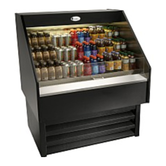
OPEN DISPLAY CASE
SSAC-40BSC
NOTIFY C AR IE R OF DAMAG E AT ONC E .
It is the responsibility of the consignee to inspect the
container upon receipt of same and to determine the
possibility of any damage, including concealed
damage. R andell suggests that if you are suspicious
of damage to make a notation on the delivery receipt.
It will be the responsibility of the consignee to file a
claim with the carrier. We recommend that you do so
at once.
Information contained in this document is known to be
current and accurate at the time of printing/creation.
Unified Brands recommends referencing our product line
websites, unifiedbrands.net, for the most updated product
information and specifications.
4/19/2006
PP MNL0602
Randell Manufacturing
Unified Brands, Inc
525 South Coldwater Rd • Weidman, MI 48893
888-994-7636 • Fax 888-864-7636 • unifiedbrands.net
Advertisement
Table of Contents

Related Manuals for Randell SSAC-40BSC


Summary of Contents for Randell SSAC-40BSC
- Page 1 & replacement parts for OPEN DISPLAY CASE SSAC-40BSC NOTIFY C AR IE R OF DAMAG E AT ONC E . It is the responsibility of the consignee to inspect the container upon receipt of same and to determine the possibility of any damage, including concealed damage.
- Page 2 18……………………………………..……Troubleshooting page 19-22…………………………….……..Replacement Parts Congratulations on your recent purchase of Randell food service equipment, and welcome to the growing family of satis ed Randell customers. Our reputation for superior products is the result of consistent quality craftsmanship. From the earliest stages of product design to successive steps in fabrication and assembly, rigid standards of excellence are maintained by out sta of designers, engineers, and skilled employees.
-
Page 3: Installation Date
In addition, all Randell food service equipment is backed by some of the best warranties in the food service industry and by our professional sta of service technicians. Retain this manual for future reference. NOTICE: Due to a continuous program of product improvement, Randell Manufacturing reserves the right to make changes in design and speci cations without prior notice. -
Page 4: Warranty P Olicies
LABOR COVERAGE In the unlikely event a Randell manufactured unit fails due to defects in materials or workmanship within the rst ninety days, Randell agrees to pay reasonable labor incurred. During the rst ninety days, work authorizations are not required for in warranty repairs. - Page 5 2. Provide repair at the manufacturing facility by requiring that the defective unit be sent back to Randell freight prepaid. Perform repair at the expense of Randell and ship the item back to the customer freight collect. 3. Furnish complete condensing unit freight collect in exchange for the...
- Page 6 Verbal quotations are provided for customer convenience only and are considered invalid in the absence of a written quotation. Written quotations from Randell are valid for 30 days from quote date unless otherwise speci ed. Randell assumes no liability for dealer quotations to end-users.
-
Page 7: Returned Goods
), Randell’s export management organization. *FOOTNOTES IN REFERENCE TO PARAGRAPHS ABOVE 1. Herein called Randell. 2. NET means list price less discount, warranty, labor policy, freight, Randell delivery and other miscellaneous charges. CASH DISCOUNTS WILL BE CALCULATED ON NET ONLY. -
Page 8: Unit Specifications
Unit S pecifications Ship Model H.P. Voltage Amps Ref / Qty NEMA R134a / 20oz SSAC40BSC 40" 34” 46.5” 115/60/1 5-15P 800-621-8560... -
Page 9: Unit Installation
S E L E C TING A L OC ATION FOR Y OUR NE W UNIT The following conditions should be considered when selecting a location for your unit: 1. Floor L oad: The area on which the unit will rest must be level, free of vibration, and suitably strong enough to support the combined weights of the unit plus the maximum product load weight 2. - Page 10 E L E C TR IC AL S UP P L Y : Any wiring should be done by a qualified electrician in accordance with local electrical codes. A properly wired and grounded outlet will assure proper operation. P lease consult the data tag attached to the compressor to ascertain the correct electrical requirements.
-
Page 11: Unit Operation
P R ODUC T P L ACE ME NT AND MAXIMUM L OAD LE VE L S 1. This unit and the shelving provided, is designed for displaying of packaged products in containers approximately 4” in height. 2. It is designed so that there is air flow over and between the containers to protect food products from warmer ambient temperatures. - Page 12 B efore making temperature adjus tments : A. Make sure that you are allowing adequate time for the cabinet temperature to equalize. can take a long time for temperatures in the display area to stabilize. B. Make sure that unit operation is not being effected by room ambient conditions.
- Page 13 Randell Control Eliwell Setting in Order By Folder Purchased / Stock Part Number Folder Code Thermostat set point Thermostat Differential (hysterisis) Upper Set Point Lower Set Point Compressor ON (probe failure) Compressor OFF (probe failure) Output delay @ Startup (Compr)
- Page 14 DIXELL CONTROL SETTING INSTRUCTIONS HOW TO CHANGE A PARAMETER VALUE To change the parameter’s value operate as follows: 1.- Enter the Programming mode by pressing the Set and Down Arrow for 3 seconds (the defrost and water drops symbol will start blinking) 2.- Select the required parameter.
-
Page 15: Preventive Maintenance
R andell strongly suggests a preventive maintenance program which would include the following Monthly procedures: 1. C leaning of all condenser coils. C ondenser coils are a critical component in the life of the compressor and must remain clean to assure proper air flow and heat transfer. - Page 16 P reventive Maintenance (cont.) P roper maintenance of equipment is the ultimate necessity in preventing costly repairs. B y evaluating each unit on a regular schedule, you can often catch and repair minor problems before they completely disable the unit and become burdensome on your entire operation.
-
Page 17: Electrical Diagram
E lectrical Diagram uni edbrands.net... -
Page 18: Troubleshooting Guide
SYMPTOM POSSIBLE CAUSE Unit doesn't run 1. No power to unit 2. Temperature control turned o 3. Temperature control faulty 4. Compressor overheated 5. Condenser fan faulty 6. Overload protector faulty 7. Compressor relay faulty 8. Compressor faulty Unit short cycles 1. -
Page 19: Item Description
FAN ASSEMBLY FRONT COVER MOUNTING FAN MOTOR RING BLADE, 200MMX28 TYPE A PLASTIC MOTOR, FAN 6W 115V/60HZ WIRE HARNESS, 36" MALE FRONT AIR RETURN OPEN DISPLAY CASE SSAC-40BSC PART # EL SHD018 EL TUB018 RP CHN0601 EL BLS0601 EL SWT0502... - Page 20 FRONT COMPRESSOR HOLD DOWN CLIP CONDENSING UNIT FILTER-DRIER POWER CORD REAR COMPRESSOR HOLD DOWN CLIP LOUVERED PANEL 2” SNAP-IN GROMMET 800-621-8560 OPEN DISPLAY CASE SSAC-40BSC PART # RP SHL0603 RP SHL0602 RP SHD0602 RP BOX0601 RP CNT0601 RF CNT0505 EL WIR0501...
Need help?
Do you have a question about the SSAC-40BSC and is the answer not in the manual?
Questions and answers