Table of Contents
Advertisement
OPERATOR'S MANUAL
This manual provides information on
installation, operating, maintenance,
trouble shooting & replacement parts for
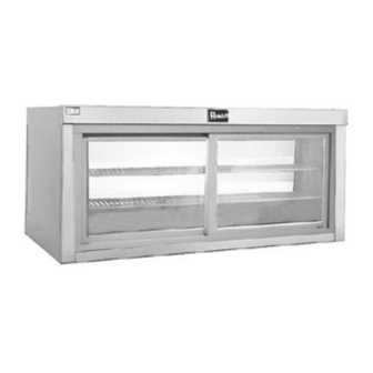
42000A Refrigerated Wall
Mount Display Merchandiser
42036A
42048A
42060A
NOTIFY CARIER OF DAMAGE AT ONCE.
It is the responsibility of the consignee to inspect the
container upon receipt of same and to determine the
possibility of any damage, including concealed
damage. Randell suggests that if you are suspicious
of damage to make a notation on the delivery receipt.
It will be the responsibility of the consignee to file a
claim with the carrier. We recommend that you do so
at once.
525 South Coldwater Road • Weidman, MI 48893
888-994-7636 • Fax 888-864-7636 • unifiedbrands.net
10/10/2008
PP MNL0807
Advertisement
Table of Contents

Related Manuals for Randell 41048A


Summary of Contents for Randell 41048A
- Page 1 Randell suggests that if you are suspicious of damage to make a notation on the delivery receipt. It will be the responsibility of the consignee to file a claim with the carrier.
-
Page 2: Table Of Contents
16………………………………………..Electrical Diagram page 17……………………………………..……Troubleshooting page 18-21…………………………….…...Replacement Parts Congratulations on your recent purchase of Randell food service equipment, and welcome to the growing family of satisfied Randell customers. Our reputation for superior products is the result of consistent quality craftsmanship. From the earliest stages of product design to successive steps in fabrication and assembly, rigid standards of excellence are maintained by our staff of designers, engineers, and skilled employees. -
Page 3: Serial Number Location
In addition, all Randell food service equipment is backed by some of the best warranties in the food service industry and by our professional staff of service technicians. Retain this manual for future reference. NOTICE: Due to a continuous program of product improvement, Randell reserves the right to make changes in design and specifications without prior notice. -
Page 4: Warranty Policies
Authorized Service Agent (ASA). Any warranty work performed by a non-ASA will not be honored by Randell. A complete listing of current ASAs can be found on the Randell page of our web site : www.unifiedbrands.net. Warranties are effective from date of shipment, with a thirty day window to allow for shipment, installation and setup. - Page 5 2. Provide repair at the manufacturing facility by requiring that the defective unit be sent back to Randell freight prepaid. Perform repair at the expense of Randell and ship the item back to the customer freight collect. 3. Furnish complete condensing unit freight collect in exchange for the return of the defective compressor sent back freight prepaid.
- Page 6 Verbal quotations are provided for customer convenience only and are considered invalid in the absence of a written quotation. Written quotations from Randell are valid for 30 days from quote date unless otherwise specified. Randell assumes no liability for dealer quotations to end-users.
-
Page 7: Returned Goods
(www.doriandrake.com), Randell’s export management organization. *FOOTNOTES IN REFERENCE TO PARAGRAPHS ABOVE 1. Herein called Randell. 2. NET means list price less discount, warranty, labor policy, freight, Randell delivery and other miscellaneous charges. CASH DISCOUNTS WILL BE CALCULATED ON NET ONLY. -
Page 8: Unit Specifications
Storage Model Cu. Ft. 42036A 36” 22.5” 20” 42048A 48” 22.5” 20” 42060A 60” 22.5” 20” 800-621-8560 8 8 8 8 Unit Specifications 42048A shown Shelves Volt Sq. Ft. ¼ 115/60/1 ¼ 115/60/1 ¼ 115/60/1 Amps NEMA Ship Wt. 5-15P 5-15P 5-15P... -
Page 9: Installation Checklist
SELECTING A LOCATION FOR YOUR NEW UNIT The following conditions should be considered when selecting a location for your unit: Wall Load: The area on which the unit will rest must be level, free of vibration, and suitably strong enough to support the combined weights of the unit plus the maximum product load weight. - Page 10 6. Carefully lift unit and lower unit onto the wall mounting bracket making sure the unit mounting bracket is securely in the wall mount bracket. 7. Assure unit is level. Shimming may be required so unit is tilting at top or bottom.
-
Page 11: Unit Operation
Randell has preset the cold control to ensure that your unit runs at an optimum temperature, but due to varying ambient conditions, including elevation, food product as well as type of operation, you may need to alter this temperature. Additional adjustments can be made (within limits) by turning the control dial up or down until the desired temperature is reached. - Page 12 Door Removal: 1. Locate outside door (sticker to identify door in lower corner of door) 2. Open door 3” 3. Lift door up 4. Pull lower part of door out away from unit. 5. Repeat for inside door Door Installation: 1.
-
Page 13: Service Connections
Door Adjustment: Roller bearings on bottom of each door may be adjusted to allow for proper seal of glass door. To look for proper door sealing assure that the bumper gasket of each door touches the entire vertical side of the door frame. No gaps should be visible NOTE: The design of the bumper gasket does allow for a small 1/8”... -
Page 14: Preventative Maintenance
Randell strongly suggests a preventive maintenance program which would include the following Monthly procedures: If a failure of the equipment is a direct result of any of the Preventative Maintenance guidelines being neglected the repairs will not be covered under warranty. - Page 15 For a complete listing of current Randell ASA please visit www.unifiedbrands.net Randell believes strongly in the products it manufactures and backs those products with one of the best warranties in the industry. We believe with the proper maintenance and use, you will realize a profitable return on your investment and years of satisfied service.
-
Page 16: Electrical Diagram
Electrical Diagram 800-621-8560... -
Page 17: Troubleshooting Guide
SYMPTOM POSSIBLE CAUSE Unit doesn't run 1. No power to unit 2. Temperature control turned off 3. Temperature control faulty 4. Compressor overheated 5. Condenser fan faulty 6. Overload protector faulty 7. Compressor relay faulty 8. Compressor faulty Unit short cycles 1. -
Page 18: Replacement Parts
Replacement 42000A Series Parts 800-621-8560... - Page 19 Replacement 42000A Series Parts unifiedbrands.net...
-
Page 20: Replacement Parts List
Replacement Parts List Item # Part # Description HD SHL005 SHELF 8 ½” X 31 7/8” HD SHL006 SHELF 8 ½” X 43 7/8” HD SHL007 SHELF 8 ½” X 55 7/8” HD FRM036 FRAME & DOOR ASSY 17” X 31 7/8” HD FRM048 FRAME &... - Page 21 Item # Part # Description RF FAN005 FAN BLADE EL MTR0230 EVAP FAN MOTOR RP BRK1050 MOTOR MOUNT BRACKET RF COI120B EVAP COIL RF FAN010 FAN GUARD RP DFL0801 EVAP HOUSING AIR DEFLECTOR RP GRD0801 COND FAN GUARD - SCREEN RP HSG0802 COND FAN HOUSING RF CMP010-134...
Need help?
Do you have a question about the 41048A and is the answer not in the manual?
Questions and answers