
Related Manuals for MSI MS-7151


Summary of Contents for MSI MS-7151
- Page 1 All manuals and user guides at all-guides.com RX480 Neo2 MS-7151 (v1.X) ATX Mainboard English Version G52-M7151X1...
- Page 2 VOIR LA NOTICE D’INSTALLATION AVANT DE RACCORDER AU RESEAU. Micro-Star International MS-7151 This device complies with Part 15 of the FCC Rules. Operation is subject to the following two conditions: (1) this device may not cause harmful interference, and (2) this device must accept any interference received, including interference that may cause undesired operation.
- Page 3 If a problem arises with your system and no solution can be obtained from the user’s manual, please contact your place of purchase or local distributor. Alternatively, please try the following help resources for further guidance. Visit the MSI website for FAQ, technical guide, BIOS updates, driver updates, and other information: http://www.msi.com.tw/program/service/faq/ faq/esc_faq_list.php...
- Page 4 All manuals and user guides at all-guides.com Safety Instructions Always read the safety instructions carefully. Keep this User’s Manual for future reference. Keep this equipment away from humidity. Lay this equipment on a reliable flat surface before setting it up. The openings on the enclosure are for air convection hence protects the equip- ment from overheating.
- Page 5 All manuals and user guides at all-guides.com WEEE Statement...
- Page 6 All manuals and user guides at all-guides.com...
- Page 7 All manuals and user guides at all-guides.com...
-
Page 8: Table Of Contents
All manuals and user guides at all-guides.com CONTENTS Chapter 1. Getting Started ..................1-1 Mainboard Specifications ..................1-2 Mainboard Layout ....................1-5 Packing Checklist ....................1-6 Chapter 2. Hardware Setup ................... 2-1 Quick Components Guide ..................2-2 Central Processing Unit: CPU ................2-3 CPU Installation Procedures for Socket 939 .......... - Page 9 All manuals and user guides at all-guides.com Slots ........................2-21 PCI Express Slots ..................2-21 PCI (Peripheral Component Interconnect) Slots ........2-22 PCI Interrupt Request Routing ..............2-22 Chapter 3. BIOS Setup ..................... 3-1 Entering Setup ...................... 3-2 Control Keys ....................3-2 Getting Help ....................
- Page 10 All manuals and user guides at all-guides.com BIOS RAID Utility Screen Description ............B-5 Description of RAID Setup Operations ............B-5 Installing RAID Drivers (for W indows 2000/XP only) ......... B-8 Installing RAID Drivers during OS Install ............B-8 Updating Previously Installed RAID Drivers ..........B-8 Installing SATARaid Utility ..................
-
Page 11: Chapter 1. Getting Started
All manuals and user guides at all-guides.com Getting Started Ch ap ter 1 . Get ti ng Started Getting Started Thank you for choosing the RX480 Neo2 (MS-7151 v1.X) ATX ® mainboard. The RX480 Neo2 mainboard is based on ATi RX480 & ®... -
Page 12: Mainboard Specifications
Mainboard Specifications † Supports 64-bit AMD ® Athlon 64 and Athlon 64 FX processor (Socket 939) † Supports up to 4200+ Athlon 64 FX or higher CPU (For the latest information about CPU, please visit http://www.msi.com.tw/pro- gram/products/mainboard/mbd/pro_mbd_cpu_support.php) Chipset † ATI ®... - Page 13 All manuals and user guides at all-guides.com Getting Started MSI Reminds You... 1. Please note that users cannot install OS, either WinME or Win98, in their SATA hard drives. Under these two OSs, SATA can only be used as an ordinary storage device.
- Page 14 All manuals and user guides at all-guides.com MS-7151 ATX Mainboard records your mainboard specifications. † Supports boot from LAN, USB Device 1.1 & 2.0, and SATA HDD. Dimension † ATX Form Factor: 30.5cm X 21.5cm M ounting † 6 mounting holes...
-
Page 15: Mainboard Layout
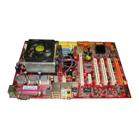
All manuals and user guides at all-guides.com Getting Started Mainboard Layout RX480 Neo2 (MS-7151 v1.X) ATX Mainboard... -
Page 16: Packing Checklist
All manuals and user guides at all-guides.com MS-7151 ATX Mainboard Packing Checklist MSI Driver/Utility CD SATA Cable (Optional) MSI motherboard Standard Cable for Standard Cable for Power Cable Floppy Disk IDE Devices USB Bracket (Optional) Back IO Shield User’s Guide * The pictures are for reference only. -
Page 17: Chapter 2. Hardware Setup
All manuals and user guides at all-guides.com Hardware Setup Chapter 2. Hardware Setup Hardware Setup This chapter tells you how to install the CPU, memory modules, and expansion cards, as well as how to setup the jumpers on the mainboard. Also, it provides the instructions on connecting the pe- ripheral devices, such as the mouse, keyboard, etc. -
Page 18: Quick Components Guide
All manuals and user guides at all-guides.com MS-7151 ATX Mainboard Quick Components Guide DDR DIMMs, p.2-7 CPU, p.2-3 JCI1, p.2-16 Back Panel I/O, p.2-10 JIR1, p.2-19 JPWR1, p.2-9 FDD1, p.2-14 JPWR2, p.2-9 NB_FAN, CPU_FAN, p.2-14 JPWR3, p.2-9 JCD1, p.2-17 IDE1/2, PCI Express p.2-15... -
Page 19: Central Processing Unit: Cpu
If you do not have the heat sink and cooling fan, contact your dealer to purchase and install them before turning on the computer. For the latest information about CPU, please visit http://www.msi.com.tw/pro- gram/products/mainboard/mbd/pro_mbd_cpu_support.php. MSI Reminds You... -
Page 20: Cpu Installation Procedures For Socket 939
All manuals and user guides at all-guides.com MS-7151 ATX Mainboard CPU Installation Procedures for Socket 939 1. Please turn off the power and unplug the power cord before Open Lever installing the CPU. Sliding 90 degree Plate 2. Pull the lever s ideways away from the socket. -
Page 21: Installing Amd Athlon64 Cpu Cooler Set
MSI Reminds You... Mainboard photos shown in this section are for demonstration of the cooler installation for Socket 939 CPUs only. The appearance of your mainboard may vary depending on the model you purchase. - Page 22 All manuals and user guides at all-guides.com MS-7151 ATX Mainboard 5. Position the cooling set onto the re- 7. Fasten down the lever. tention mechanism. Hook one end of the clip to hook first, and then press down the other...
-
Page 23: Memory
Single Channel 128MB~1GB 128MB~1GB Dual Channel MSI Reminds You... - The system operates ONLY when the DDR modules are installed in accordance with the above-mentioned memory population rules. - In dual-channel mode, make sure that you install memory modules of the same type and density on DDR DIMMs. -
Page 24: Installing Ddr Modules
All manuals and user guides at all-guides.com MS-7151 ATX Mainboard Installing DDR Modules The DDR DIMM has only one notch on the center of module. The module will only fit in the right orientation. Insert the DIMM memory module vertically into the DIMM slot. Then push it in until the golden finger on the memory module is deeply inserted in the socket. -
Page 25: Power Supply
JPWR2 SIGNAL JPWR3 MSI Reminds You... 1. These two connectors connect to the ATX power supply and have to work together to ensure stable operation of the mainboard. 2. Power supply of 350 watts (and above) is highly recommended for system stability. -
Page 26: Back Panel
All manuals and user guides at all-guides.com MS-7151 ATX Mainboard Back Panel L-In RS-Out Parallel M ou se L-Out CS-Out Keyboard COM Port USB Ports SPDIF-Out Mouse/Keyboard Connector ® The mainboard provides a standard PS/2 mouse/keyboard mini DIN connector ®... -
Page 27: Serial Port Connector: Com Port
All manuals and user guides at all-guides.com Hardware Setup Serial Port Connector: COM Port The mainboard offers one 9-pin male DIN connector COM Port. It’s a 16550A high speed communication port that send/receive/ 16 bytes FIFOs. You can attach a serial mouse or other serial device directly to it. -
Page 28: Parallel Port Connector: Lpt1
All manuals and user guides at all-guides.com MS-7151 ATX Mainboard Parallel Port Connector: LPT1 The mainboard provides a 25-pin female centronic connector as LPT. A parallel port is a standard printer port that supports Enhanced Parallel Port (EPP) and Ex- tended Capabilities Parallel Port (ECP) mode. -
Page 29: Audio Port Connectors
(Surround R/L) (in 7.1 CH) Center/Subwoofer Speaker Out Line Out ( in 7.1CH / 5.1CH) (Front R/L) M IC SPDIF-Out MSI Reminds You... For the advanced functions of the audio codec, please refer to Appen- dix A for details. 2-13... -
Page 30: Connectors
All manuals and user guides at all-guides.com MS-7151 ATX Mainboard Connectors Floppy Disk Drive Connector: FDD1 The mainboard provides a standard floppy disk drive connector that supports 360K, 720K, 1.2M, 1.44M and 2.88M floppy disk types. FDD1 Fan Power Connectors: CPU_FAN /NB_FAN/SYS_FAN The fan power connectors support system cooling fan with +12V. -
Page 31: Ata133 Hard Disk Connectors: Ide1 & Ide2
IDE2 (Secondary IDE Connector) IDE2 can also connect a Master and a Slave drive. MSI Reminds You... If you install two hard disks on cable, you must configure the second drive to Slave mode by setting its jumper. Refer to the hard disk docu- mentation supplied by hard disk vendors for jumper setting instructions. -
Page 32: Serial Ata Connectors: Sata1~Sata4
All manuals and user guides at all-guides.com MS-7151 ATX Mainboard Serial ATA Connectors: SATA1~SATA4 The ATI SB400 SouthBridge supports four serial ATA connectors SATA1~SATA4. SATA1~SATA4 are high-speed Serial ATA interface ports. Each supports 1 genera- tion serial ATA data rates of 150MB/s and is fully compliant with Serial ATA 1.0 specifications. -
Page 33: Cd-In Connector: Jcd1
Left channel audio signal to front panel AUD_RET_L Left channel audio signal return from front panel MSI Reminds You... If you don’t want to connect to the front audio header, pins 5 & 6, 9 & 10 have to be jumpered in order to have signal output directed to the rear audio ports. -
Page 34: Serial Port Header: Com1 (Optional)
All manuals and user guides at all-guides.com MS-7151 ATX Mainboard Serial Port Header: JCOM1 (Optional) The mainboard offers one 9-pin header as serial port. The port is a 16550A high speed communication port that sends/receives 16 bytes FIFOs. You can attach a serial mouse or other serial device directly to it. -
Page 35: Irda Infrared Module Header: Jir1 (Optional)
USB1- USB0+ USB1+ JUSB1, JUSB2 (USB 2.0) Key (no pin) USBOC Connected to JUSB1 or JUSB2 USB 2.0 Bracket (Optional) MSI Reminds You... Note that the pins of VCC and GND must be connected correctly to avoid possible damage. 2-19... -
Page 36: Jumpers
All manuals and user guides at all-guides.com MS-7151 ATX Mainboard Jumpers The motherboard provides the following jumpers for you to set the computer’s function. This section will explain how to change your motherboard’s function through the use of jumpers. Clear CMOS Jumper: JCMOS1 There is a CMOS RAM onboard that has a power supply from external battery to keep the data of system configuration. -
Page 37: Slots
All manuals and user guides at all-guides.com Hardware Setup Slots The mainboard provides a PCI Express x16 slot, a PCI Express x1 slot and four 32-bit PCI bus slots. PCI Express Slots The PCI Express slots support high-bandwidth, low pin count, and serial interconnect technology. -
Page 38: Pci (Peripheral Component Interconnect) Slots
All manuals and user guides at all-guides.com MS-7151 ATX Mainboard PCI (Peripheral Component Interconnect) Slots The PCI slots allow you to insert the expansion cards to meet your needs. W hen adding or removing expansion cards, make sure that you unplug the power supply first. -
Page 39: Chapter 3. Bios Setup
² You want to change the default settings for customized features. MSI Reminds You... 1. The items under each BIOS category described in this chap- te r a re u nde r c ont inu ous upd ate fo r b ette r s y s t em performance. -
Page 40: Entering Setup
All manuals and user guides at all-guides.com M S-7151 ATX M ainboard Entering Setup Power on the computer and the system will start POST (Power On Self Test) process. W hen the message below appears on the screen, press <DEL> key to enter Setup. -
Page 41: Control Keys
The preset Optimal Defaults of the BIOS setup program provide optimal perfor- mance settings for all devices and the system. MSI Reminds You... The items under each BIOS category described in this chapter are under continuous update for better system performance. -
Page 42: The Main Menu
All manuals and user guides at all-guides.com M S-7151 ATX M ainboard The Main Menu Once you enter AMIBIOS NEW SETUP UTILITY, the Main Menu will appear on the screen. Use arrow keys to move among the items and press <Enter> to enter the sub-menu. - Page 43 All manuals and user guides at all-guides.com BIOS Setup Cell M enu Use this menu to specify your settings for frequency/voltage control. Load Fail-Safe Defaults Use this menu to load the default values set by the BIOS vendor for stable system performance.
-
Page 44: Standard Cmos Features
All manuals and user guides at all-guides.com M S-7151 ATX M ainboard Standard CMOS Features The items in Standard CMOS Features Menu includes some basic setup items. Use the arrow keys to highlight the item and then use the <+> or <-> keys to select the value you want in each item. - Page 45 All manuals and user guides at all-guides.com BIOS Setup Device This item shows the information about the specified item. Read-only. Type This item defines the HDD parameters. LBA/Large M ode This item allows you to enable or disable the LBA (Logical Block Address, the logical block size in hard disk) mode.
- Page 46 All manuals and user guides at all-guides.com M S-7151 ATX M ainboard System Information Press <Enter> to for the sub-menu of each item: Total System M emory/BIOS Version This item shows the memory status and BIOS version of your system (read only).
-
Page 47: Advanced Bios Features
All manuals and user guides at all-guides.com BIOS Setup Advanced BIOS Features Quick Booting Setting the item to [Enabled] allows the system to boot within 5 seconds since it will skip some check items. Available options: [Enabled], [Disabled]. Boot Sector Protection This function protects the BIOS from accidental corruption by unauthorized users or computer viruses. - Page 48 Setting the option to [Yes] allows the system to try to boot from other devices if the system fails to boot from the 1st/2nd/3rd boot device. Set- tings are: [Yes], [No]. MSI Reminds You... Available settings for “1st/2nd/3rd Boot Device” vary depending on the bootable devices you have installed. For example, if you did not install a floppy drive, the setting “Floppy”...
-
Page 49: Advanced Chipset Features
All manuals and user guides at all-guides.com BIOS Setup Advanced Chipset Features MSI Reminds You... Change these settings only if you are familiar with the chipset. DRAM Timing The value in this field depends on performance parameters of the installed memory chips (DRAM). -
Page 50: Integrated Peripherals
All manuals and user guides at all-guides.com M S-7151 ATX M ainboard Integrated Peripherals USB Controller This setting is used to enable/disable the onboard USB host controller. Setting options: [Disabled], [Enabled]. USB Device Legacy Support Set to [Enabled] if you need to use any USB 1.1/2.0 device in the operating system that does not support or have any USB 1.1/2.0 driver installed, such as DOS. - Page 51 All manuals and user guides at all-guides.com BIOS Setup IDE Devices Configuration Press <Enter> to enter the sub-menu and the following screen appears: On-Chip IDE Controller The integrated peripheral controller contains a IDE interface with support for two IDE channels. Select [Enabled] to activate the IDE interface. Set- tings options: [Disabled], [Primary], [Secondary], [Both].
- Page 52 All manuals and user guides at all-guides.com M S-7151 ATX M ainboard OnChip SATA Type Select [Enable SATA As IDE] if you want to have SATA as IDE function, and this device is able to install OS. Select [Enable SATA As RAID] if you want to have RAID function, you may install OS on this SATA device.
- Page 53 All manuals and user guides at all-guides.com BIOS Setup Power Management Features MSI Reminds You... S3-related functions described in this section are available only when your BIOS supports S3 sleep mode. ACPI Function This item is to activate the ACPI (Advanced Configuration and Power Manage- ment Interface) Function.
- Page 54 All manuals and user guides at all-guides.com M S-7151 ATX M ainboard card when system wakes up (resumes) from S3 sleep state. The system resume time is shortened when you disable the function, but system will need an AGP driver to initialize the VGA card. Therefore, if the AGP driver of the card does not support the initialization feature, the display may work abnormally or not function after resuming from S3.
- Page 55 Time (HH:MM:SS) 00 ~ 23 : 00 ~ 59 : 00 ~ 59 MSI Reminds You... If you have changed this setting, you must let the system boot up until it enters the operating system, before this function will work.
-
Page 56: Pnp/Pci Configurations
All manuals and user guides at all-guides.com M S-7151 ATX M ainboard PNP/PCI Configurations This section describes configuring the PCI bus system and PnP (Plug & Play) feature. PCI, or Peripheral Component Interconnect, is a system which allows I/O devices to operate at speeds nearing the speed the CPU itself uses when communicating with its special components. - Page 57 All manuals and user guides at all-guides.com BIOS Setup [32], [64], [96], [128]. IRQ Resource Setup Press <Enter> and the following sub-menu appears. IRQ 3/4/5/7/9/10/11/14/15 These items specify the bus where the specified IRQ line is used. The settings determine if AMIBIOS should remove an IRQ from the pool of available IRQs passed to devices that are configurable by the system BIOS.
-
Page 58: H/W Monitor
All manuals and user guides at all-guides.com M S-7151 ATX M ainboard H/W Monitor This section shows the status of your CPU, fan, overall system status, etc. Monitor function is available only if there is hardware monitoring mechanism CPU Shutdown Temperature If the CPU temperature reaches the limit preset in the next setting, the system will shutdown automatically. - Page 59 All manuals and user guides at all-guides.com BIOS Setup the contrary, if the CPU fan current temperature is lower than the specified value, the CPU fan will slow down its speed to keep the temperature stable. Smart FAN Tolerance This item allows you to set the tolerance value of the smart fan. PC Health Status Press <Enter>...
-
Page 60: Cell Menu
Cell Menu The items in Cell Menu includes some important settings of CPU, AGP, DRAM and overclocking functions. MSI Reminds You... Change these settings only if you are familiar with the chipset. Current CPU Clock, Current DDR Memory Frequency These two items show the current clocks of CPU & DDR memory frequency. - Page 61 All manuals and user guides at all-guides.com BIOS Setup will automatically change in ac cordance with the setting of Adjust DDR M emory Frequency. Please note you must reboot the system to let the change take effect. Setting options: [100 MHz], [133MHz], [166MHz], [200MHz]. Adjust CPU FSB Frequency This item allows you to select the CPU Front Side Bus clock frequency (in MHz) and overclock the processor by adjusting the FSB clock to a higher frequency.
- Page 62 Options: [Disabled], [Enabled]. MSI Reminds You... The settings shown in different color in CPU Voltage, DDR Volt- age and NB Voltage help to verify if your setting is proper for your system.
-
Page 63: Bios Setting Password
All manuals and user guides at all-guides.com BIOS Setup BIOS Setting Password W hen you select this function, a message as below will appear on the screen: Type the password, up to six characters in length, and press <Enter>. The password typed now will replace any previously set password from CMOS memory. -
Page 64: Load Fail-Safe/Optimized Defaults
All manuals and user guides at all-guides.com M S-7151 ATX M ainboard Load Fail-Safe/Optimized Defaults The two options on the main menu allow users to restore all of the BIOS settings to the default Fail-Safe or Optimized values. The Optimized Defaults are the default values set by the mainboard manufacturer specifically for optimal performance of the mainboard. -
Page 65: Appendix A: Using 2-, 4- & 6-Channel Audio Function
All manuals and user guides at all-guides.com Using 2-, 4-, 6- or 8- Channel Audio Function Appendix A: Using 2-, 4-, 6- or 8- Channel Audio Function The mainboard is equipped with Realtek ALC850 chip, which provides support for 8-channel audio output, including 2 Front, 2 Rear, 1 Center and 1 Subwoofer channel. -
Page 66: Installing The Audio Driver
All manuals and user guides at all-guides.com MS-7151 ATX Mainboard Installing the Audio Driver You need to install the driver for Realtek ALC850 codec to function properly before you can get access to 2-, 4-, 6- or 8- channel audio operations. Follow the procedures described below to install the drivers for different operating systems. - Page 67 All manuals and user guides at all-guides.com Using 2-, 4-, 6- or 8- Channel Audio Function 3. Click Next to install the AC’97 Audio software. Clic k he r e 4. Click Finish to restart the system. Se le ct this o ptio n Clic k he r e...
-
Page 68: Software Configuration
All manuals and user guides at all-guides.com MS-7151 ATX Mainboard Software Configuration After installing the audio driver, you are able to use the 2-, 4-, 6- or 8- channel audio feature now. Click the audio icon from the system tray at the lower-right corner of the screen to activate the AC97 Audio Configuration. -
Page 69: Sound Effect
All manuals and user guides at all-guides.com Using 2-, 4-, 6- or 8- Channel Audio Function Sound Effect Here you can select a sound effect you like from the Environment list. Edit You may also edit the properties for an environment as you wish by clicking the “Edit”... - Page 70 All manuals and user guides at all-guides.com MS-7151 ATX Mainboard You may choose the provided sound effects, and the equalizer will adjust automatically. If you like, you may also load an equalizer setting or make an new equalizer setting to save as an new one by using the “Load EQ Setting” and “Save Preset”...
-
Page 71: Speaker Configuration
All manuals and user guides at all-guides.com Using 2-, 4-, 6- or 8- Channel Audio Function Speaker Configuration In this tab, you can easily configure your multi-channel audio function and speakers. 1. First you have to select the audio configuration below which is identical to the audio jack on your mainboard. - Page 72 All manuals and user guides at all-guides.com MS-7151 ATX Mainboard Select the speaker by clicking it to test its functionality. The one you select will light up and make testing sound. If any speaker fails to make sound, then check whether the cable is inserted firmly to the connector or replace the bad speakers with good ones.
-
Page 73: Hrtf Demo
All manuals and user guides at all-guides.com Using 2-, 4-, 6- or 8- Channel Audio Function HRTF Demo In this tab you may adjust your HRTF (Head Related Transfer Functions) 3D positional audio before playing 3D audio applications like gaming. You may also select different environment to choose the most suitable environment you like. -
Page 74: General
All manuals and user guides at all-guides.com MS-7151 ATX Mainboard General In this tab it provides some information about this AC97 Audio Configuration utility, including Audio Driver Version, DirectX Version, Audio Controller & AC97 Codec. You may also select the language of this utility by choosing from the Language list. -
Page 75: Using 2-, 4- & 6- Channel Audio Function
All manuals and user guides at all-guides.com Using 2-, 4-, 6- or 8- Channel Audio Function SPDIF In this tab it provides options about SPDIF-Out for you to configure. † No Output: W ith this option, there is no S/PDIF output signal while playing analog and digital audio. - Page 76 All manuals and user guides at all-guides.com MS-7151 ATX Mainboard Using 2-, 4-, 6- & 8- Channel Audio Function Connecting the Speakers W hen you have set the Multi-Channel Audio Function mode properly in the software utility, connect your speakers to the correct phone jacks in accordance with the setting in software utility.
- Page 77 All manuals and user guides at all-guides.com Using 2-, 4-, 6- or 8- Channel Audio Function n 4-Channel Mode for 4-Speaker Output Description: Connect two speakers to back panel’s Line Out connector and two speakers to the real-chan- 4-Channel Analog Audio Output nel Line Out connector.
- Page 78 All manuals and user guides at all-guides.com MS-7151 ATX Mainboard n 6-Channel Mode for 6-Speaker Output Description: Connect two speakers to back panel’s Line Out connector, two speakers to the rear-channel 6-Channel Analog Audio Output and two speakers to the cen- ter/subwoofer-channel Line Out connectors.
- Page 79 All manuals and user guides at all-guides.com Using 2-, 4-, 6- or 8- Channel Audio Function n 8-Channel Mode for 8-Speaker Output Description: Connect two speakers to back panel’s Line Out connector, two speakers to the rear-channel, 8-Channel Analog Audio Output two speakers to the c enter/ subwoofer-channel Line Out connectors, and two speakers...
-
Page 80: Appendix B: Ati Sata Raid Setup Guide
All manuals and user guides at all-guides.com ATI SATA RAID Setup Guide Appendix B: ATI SATA RAID Setup Guide Two major challenges facing the storage industry today are (1): keep pace with increasing performance demands of computer systems by improving disk I/O throughput, and (2): provide data accessibility in the event of hard disk failure. -
Page 81: Sata Raid Features
All manuals and user guides at all-guides.com MS-7151 ATX Mainboard SATA RAID Features u RAID 0 and RAID 1 u On-line Mirror Rebuilding u RAID GUI Monitoring Utility: - Displays/Logs/Alerts Users to Vital RAID Set Information - Manages RAID Set Functions (configures, rebuilds, etc.) -
Page 82: Disk Mirroring (Raid 1
All manuals and user guides at all-guides.com ATI SATA RAID Setup Guide Disk Mirroring (RAID 1) Disk mirroring creates an identical twin for a selected disk by having the data simul- taneously written to two disks. This redundancy provides protection from a single disk failure. -
Page 83: Creating Raid Sets
All manuals and user guides at all-guides.com MS-7151 ATX Mainboard Creating RAID Sets Creating and deleting RAID sets and performing other RAID setting up operations are done in the BIOS. During bootup, a screen similar to the one below will appear for about 5 seconds. -
Page 84: Bios Raid Utility Screen Description
All manuals and user guides at all-guides.com ATI SATA RAID Setup Guide BIOS RAID Utility Screen Description u M ain M enu The Main Menu in the upper left corner is used to choose the operation to be performed. The selections are: 1. - Page 85 All manuals and user guides at all-guides.com MS-7151 ATX Mainboard strategy. RAID sets can be created either automatically, or to allow the greatest flexibility, manually. 1. Select “Create RAID Set.” 2. Choose a RAID 0 Striped, or a RAID 1 Mirrored set.
- Page 86 All manuals and user guides at all-guides.com ATI SATA RAID Setup Guide 1. Select “Resolve Conflicts” 2. Select the “Invalid RAID drive” entry in the Logical Drive Status window and press Enter. 3. Follow the prompts to resolve the conflict. Note that some conflict resolutions may result in the drive letter assignment changing;...
-
Page 87: Installing Raid Drivers (For W Indows 2000/Xp Only
All manuals and user guides at all-guides.com MS-7151 ATX Mainboard Installing RAID Drivers (for Windows 2000/XP only) Installing RAID Drivers during OS Install Follow the instructions in this section if you are performing a new installation of the OS (W indows 2000/XP), and wish to boot from a RAID drive connected to the SATA controller. - Page 88 All manuals and user guides at all-guides.com ATI SATA RAID Setup Guide T he following screen shots are taken from the AT I driv er installation wizard.
- Page 89 All manuals and user guides at all-guides.com MS-7151 ATX Mainboard B-10...
-
Page 90: Installing Sataraid Utility
All manuals and user guides at all-guides.com ATI SATA RAID Setup Guide Installing SATARaid Utility Insert your W indows 2000/XP ATI driver CD into the CD-ROM/DVD drive. Run the setup.exe program on the CD and follow the setup instructions to complete the installation. - Page 91 All manuals and user guides at all-guides.com MS-7151 ATX Mainboard SATARaid GUI can be launched from the Task Bar B-12...
-
Page 92: Sataraid Gui
All manuals and user guides at all-guides.com ATI SATA RAID Setup Guide SATARaid GUI The SATARaid GUI offers the user the ability to easily monitor the RAID Set. To launch the GUI, simply double-click on the icon located in the bottom right hand corner of the Desktop. - Page 93 All manuals and user guides at all-guides.com MS-7151 ATX Mainboard A RAID 1 Set Monitoring Example B-14...
- Page 94 All manuals and user guides at all-guides.com ATI SATA RAID Setup Guide B-15...
- Page 95 All manuals and user guides at all-guides.com MS-7151 ATX Mainboard B-16...
- Page 96 All manuals and user guides at all-guides.com ATI SATA RAID Setup Guide A RAID 0 Set Monitoring Example B-17...
- Page 97 All manuals and user guides at all-guides.com MS-7151 ATX Mainboard B-18...
- Page 98 All manuals and user guides at all-guides.com ATI SATA RAID Setup Guide B-19...
- Page 99 All manuals and user guides at all-guides.com MS-7151 ATX Mainboard B-20...
- Page 100 All manuals and user guides at all-guides.com ATI SATA RAID Setup Guide B-21...
- Page 101 All manuals and user guides at all-guides.com MS-7151 ATX Mainboard B-22...
- Page 102 All manuals and user guides at all-guides.com ATI SATA RAID Setup Guide B-23...
-
Page 103: Configuring Raid 0 Set(S) With Windows Disk Manager
All manuals and user guides at all-guides.com MS-7151 ATX Mainboard Configuring RAID 0 Set(s) with Windows Disk Manager Note: This section is only applicable to non-initiated drives. It is not applicable if the drives have been set up as RAID 0 with the BIOS utility. - Page 104 All manuals and user guides at all-guides.com ATI SATA RAID Setup Guide If SATA drives had not been initialized, initialize the disk as Dynamic. Right click on Disk 0 and select ‘New Volume’. At ‘New Volume W izard’ select Striped for type of volume.
- Page 105 All manuals and user guides at all-guides.com MS-7151 ATX Mainboard Total size of disk set for striping is set next. B-26...
- Page 106 All manuals and user guides at all-guides.com ATI SATA RAID Setup Guide B-27...
- Page 107 All manuals and user guides at all-guides.com MS-7151 ATX Mainboard B-28...
Need help?
Do you have a question about the MS-7151 and is the answer not in the manual?
Questions and answers