Sign In
Upload
Download
Table of Contents
Contents
Add to my manuals
Delete from my manuals
Share
URL of this page:
HTML Link:
Bookmark this page
Add
Manual will be automatically added to "My Manuals"
Print this page
×
Bookmark added
×
Added to my manuals
Manuals
Brands
MSI Manuals
Motherboard
RS482M4-CSIP
Manual
MSI RS482M4-CSIP Manual
Micro-atx mainboard v1.x
Hide thumbs
1
2
3
4
5
6
7
Table Of Contents
8
9
10
11
12
13
14
15
16
17
18
19
20
21
22
23
24
25
26
27
28
29
30
31
32
33
34
35
36
37
38
39
40
41
42
43
44
45
46
47
48
49
50
51
52
53
54
55
56
57
58
59
60
61
62
63
64
65
66
67
68
69
70
71
72
73
74
75
76
77
78
79
80
81
82
83
84
85
86
87
88
89
90
91
92
93
94
95
96
97
98
99
100
101
102
103
104
105
106
107
108
109
110
111
112
113
114
115
116
117
118
119
120
121
122
123
124
125
126
127
128
129
130
131
132
133
134
135
136
137
138
139
140
141
142
143
144
145
146
147
148
149
150
151
152
153
154
155
156
157
158
page
of
158
Go
/
158
Contents
Table of Contents
Bookmarks
Table of Contents
Copyright Notice
Safety Instructions
Technical Support
WEEE Statement
Table of Contents
Chapter 1. Getting Started
Mainboard Specifications
Mainboard Layout
Packing Checklist
Chapter 2. Hardware Setup
Quick Components Guide
Central Processing Unit: CPU
CPU Installation Procedures for Socket 939
Installing AMD Athlon64 CPU Cooler Set
Memory
DIMM Module Combination
Installing DDR Modules
Power Supply
ATX 24-Pin Power Connector: ATX1
ATX 12V Power Connector: JPW1
Back Panel
Mouse/Keyboard Connector
VGA Connector
Digital Panel Connector
USB Connectors
LAN (RJ-45) Jack:10/100 LAN (8100C)
Audio Port Connectors & Audio Header (J1)
IEEE 1394 Port
Parallel Port Connector: LPT1
Connectors
Floppy Disk Drive Connector: FDD1
Fan Power Connectors: CPU_FAN / SYS_FAN
ATA133 Hard Disk Connectors: IDE1 & IDE2
Serial ATA Connectors: SATA1~SATA4
CD-In Connector: JCD1
Front Panel Audio Connector: JAUD1
Chassis Intrusion Switch Connector: JCI1
Audio-Out Connector: J1
Serial Port Header: JCOM2
IEEE 1394 Connectors: J1394_1
Front Panel Connector: JFP1
Front USB Connectors: JUSB1/ JUSB2
TV-Out Connector: JTV1
Jumpers
Clear CMOS Jumper: JCMOS
Slots
PCI Express Slots
PCI (Peripheral Component Interconnect) Slots
PCI Interrupt Request Routing
Chapter 3. BIOS Setup
Entering Setup
Control Keys
Getting Help
The Main Menu
Standard CMOS Features
Advanced BIOS Features
Advanced Chipset Features
Integrated Peripherals
Power Management Setup
PNP/PCI Configurations
PC Health Status
Cell Menu
Load Fail-Safe/ Optimimed Defaults
BIOS Setting Password
Chapter 4. Introduction to Digicell
Main
Introduction
H/W Diagnostic
Communication
Software Access Point
Terminology
Access Point Mode
WLAN Card Mode
Live Update
Mega Stick
Basic Function
Non-Unicode Programs Supported
PC Alert
Power on Agent
Power off / Restart
Start with
Auto Login
Appendix A: Using 2-, 4-, 6- & 8- Channel Audio Function
Installing the Audio Driver
Installation for Windows 2000/XP
Software Configuration
Sound Effect
Mixer
Audioio
S/Pdif
Microphone
3D Audio Demo
Information
Using 2-, 4-, 6- & 8- Channel Audio Function
Appendix B: ATI SATA RAID Setup Guide
SATA RAID Features
Disk Striping (RAID 0
Disk Mirroring (RAID 1
Creating RAID Sets
BIOS RAID Utility Screen Description
Description of RAID Setup Operations
Installing RAID Drivers (for Windows 2000/XP Only
Installing RAID Drivers During os Install
Updating Previously Installed RAID Drivers
Installing Sataraid Utility
Sataraid GUI
Configuring RAID 0 Set(S) with Windows Disk Manager
Appendix C: ATI SURROUNDVIEW
Getting Started
System Requirements
Installing a Graphics Card
Before You Begin
Basic Graphics Card Installation
Enabling SURROUNDVIEWTM
Frequently Asked Questions
Using Multiple Displays
Setting up Multiple Displays
Using SURROUNDVIEWTM
Business Applications
Games
Appendix D: Using the TV-Out Function (HDTV-Out Integrated
Installing the TV-Out Bracket
Connecting S-Video/ RCA & HDTV Cables
Display Setup
Advertisement
Quick Links
1
Mainboard Specifications
2
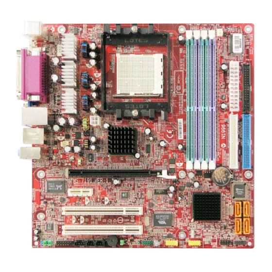
Mainboard Layout
3
Memory
4
Front Panel Connector: Jfp1
Download this manual
RS482M4-CSIP
MS-7191 (v1.X) Micro-ATX Mainboard
G52-M7191X7
i
Table of
Contents
Previous
Page
Next
Page
1
2
3
4
5
Advertisement
Table of Contents
Need help?
Do you have a question about the RS482M4-CSIP and is the answer not in the manual?
Ask a question
Questions and answers
Related Manuals for MSI RS482M4-CSIP
Motherboard MSI MS-7003 User Manual
(v1.x) microatx mainboard (103 pages)
Motherboard MSI MS-7173 User Manual
Ms-7173 (v2.x) mainboard (107 pages)
Motherboard MSI MS-7173 User Manual
(v1.x) m-atx mainboard (125 pages)
Motherboard MSI RC410M-L - MBOX - 0 MB RAM User Manual
Ms-7173 (v1.x) m-atx mainboard (135 pages)
Motherboard MSi MS-7031 User Manual
Ms-7031 (v1.x) m-atx mainboard (75 pages)
Motherboard MSI MS-9804 User Manual
Msi ms-9804 motherboard: user guide (70 pages)
Motherboard MSI RX480M2 MS-7093 User Manual
(v1.x) m-atx mainboard (131 pages)
Motherboard MSI RS482M2 Manual
M-atx mainboard (136 pages)
Motherboard MSI RX480 Neo2 User Manual
Atx mainboard (80 pages)
Motherboard MSI MS-7151 Operation User's Manual
Atx mainboard (107 pages)
Motherboard MSI RC410 Series Manual
(31 pages)
Motherboard MSI RS480M Manual
M-atx mainboard (106 pages)
Motherboard MSI RS482M Manual
M-atx mainboard (106 pages)
Motherboard MSI RS350 Quick Reference
(9 pages)
Motherboard MSI RS482M4 Series Manual
Ms-7191 (v1.x) micro-atx mainboard (158 pages)
Motherboard MSI MSI-5149 User Manual
Pentium tr10 mainboard (70 pages)
This manual is also suitable for:
Ms-7191
Table of Contents
Save PDF
Print
Rename the bookmark
Delete bookmark?
Delete from my manuals?
Login
Sign In
OR
Sign in with Facebook
Sign in with Google
Upload manual
Upload from disk
Upload from URL


Need help?
Do you have a question about the RS482M4-CSIP and is the answer not in the manual?
Questions and answers