
Related Manuals for Cypress CY3633


Summary of Contents for Cypress CY3633
- Page 1 CY3633 WirelessUSB™ LS Gaming DVK User’s Guide Version 1.1 Cypress Semiconductor 3901 North First Street San Jose, CA 95134 Tel.: (800) 858-1810 (toll-free in the U.S.) (408) 943-2600 www.cypress.com...
- Page 2 Warranty Disclaimer and Limited Cypress products, expressly or by implication. Cypress’s products are not authorized for use Liability as critical components in life support devices Cypress Corporation makes no warranty for or systems. the use of its products, other than those WirelessUSB is a trademark of the Cypress expressly contained in the Company’s stan-...
-
Page 3: Table Of Contents
Table of Contents Introduction ............1 Quick Start Using the Pre-programmed Chips . -
Page 5: Introduction
WirelessUSB™ LS Gaming DVK User’s Guide Introduction The WirelessUSB LS CY3633 Gaming DVK is an add-on to the WirelessUSB LS CY3632 DVK. The Gaming DVK is intended to serve the gaming industry by providing example wireless solutions for the XBOX and PlayStation2 (PS2) gaming platforms. -
Page 6: Quick Start Using The Pre-Programmed Chips
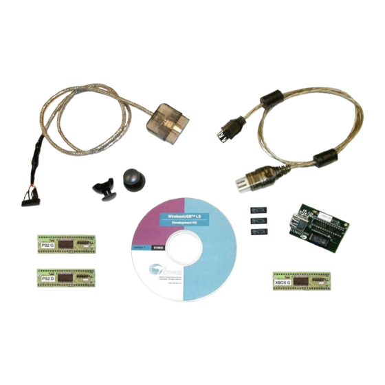
WirelessUSB™ LS Gaming DVK User’s Guide The following diagram shows the contents of the CY3633 WirelessUSB LS Gaming DVK. PlayStation2 XBOX USB Interface Cable Adapter Cable Joystick Knobs CD-ROM USB Hub Adapter Board "PS2 G" PSoC Module Blank USB PS2 G... - Page 7 XBOX USB interface. Note: The Platform Board and the standard USB cable are supplied with the standard CY3632 WirelessUSB LS DVK (they are not included in the CY3633 WirelessUSB LS Gaming DVK). Figure 3. USB Hub Adapter Board installed into Platform Board (XBOX Receiver Dongle) WirelessUSB™...
- Page 8 WirelessUSB™ LS Gaming DVK User’s Guide The Game Controller has a PSoC™ device labeled “XBOX G” installed into socket U3 of the Plat- form Board. The Game Controller can be powered with batteries or the provided power supply connected to J5 (DC power jack). To configure the XBOX system, perform the following steps: 1.
- Page 9 The mapping of the XBOX Game Controller joysticks, analog buttons, and digital buttons on the Platform Board is shown in Figure 5. The eight potentiometers on the Platform Board act as analog buttons, where clockwise rotation behaves as a depressed button, while fully counterclockwise rotation behaves as a released button.
-
Page 10: Playstation2 Quick Start Guide
WirelessUSB™ LS Gaming DVK User’s Guide 2.2 PlayStation2 Quick Start Guide The PlayStation2 system hardware configuration is shown in Figure 6. PlayStation2 Game Console Joystick Knobs "PS2 G" "PS2 D" Module Module Dongle/Receiver Platform Board Game Controller Platform Board (without Joysticks or Potentiometers) (with Joysticks and Potentiometers) Figure 6. - Page 11 The PlayStation2 Game Controller is supported by the Platform Board assembly (121-07500*G) with the PSoC™ device labeled “PS2 G” installed into socket U3. The Game Controller can be powered with batteries or with the provided DC power supply connected to J5. To configure the PS2 system, perform the following steps: 1.
-
Page 12: Auto-Bind Operation
WirelessUSB™ LS Gaming DVK User’s Guide 2.3 Auto-Bind Operation Out of the box, both gaming systems are configured to auto-bind. Additionally, the Game Control- ler is enabled to sleep if the connection is lost. Binding is performed by simultaneously pushing the Bind button on both the receiver Platform Board and the Game Controller Platform Board. -
Page 13: Game Controller Calibration Process
2.4 Game Controller Calibration Process For optimal performance, the Game Controller’s analog inputs must be calibrated. When the Game Controller goes through the calibration process, it will memorize the unique characteristics of the potentiometers and joysticks ensuring that the full range of resolution will be obtained. The calibration constants are stored in the PSoC™... -
Page 14: Xbox Firmware Development
The development environment for the CY7C65113 chip is provided by the CY3654-PO3 Develop- ment Platform. More information about the CY3654-P03 development kit can be found at www.cypress.com (Click on the USB Full-Speed Peripherals link −> Developer Kits −> CY3654 + CY3654-P03). -
Page 15: Using The Usb Chip Emulator
3.1.4 Using the USB Chip Emulator The CY3654 and the CY3654-PO3 personality board together form the complete in-circuit emula- tor (ICE) for the CY7C65113 USB Hub. Figure 9 shows the complete development system. The following steps describe this configuration • Remove the CY7C65113 chip from socket U2 on the USB Hub Adapter Board (PDC-9146) by pressing down on the black portion and sliding it away from the on-board USB connec- tors. -
Page 16: Programming
The Hi-Lo programmer can be used to program the CY7C65113. More infor- mation on the Hi-Lo programmer can be found at www.cypress.com (Click on the USB Full-Speed Peripherals link −> Developer Kits −> Cypress full-speed USB M8 Series Hi-Lo Programmer CY3649-xxxV). -
Page 17: Xbox Memory Unit Support
As noted earlier, development for the PSoC device requires the PSoC ICE-4000. The ICE and other associated development peripherals can be found at Cypress MicroSystems’ website at www.cypressmicro.com. This document assumes that the reader is familiar with the tool. The... -
Page 18: Compiling And Programming
WirelessUSB™ LS Gaming DVK User’s Guide The figure below shows the connections required for Game Controller firmware development. Figure 10. Game Controller Hardware Configuration for Firmware Development 3.2.2 Compiling and Programming Copy the Game Controller files along with the lib directory located under the WirelessUSB LS Gaming DVK directory to a directory on your hard-drive. -
Page 19: Playstation2 Firmware Development
XBOX Game Controller development as noted in section 3.2. Both the receiver dongle and Game Controller use the PSoC Designer development system. Information regarding the PSoC develop- ment environment can be found at Cypress MicroSystems’ website at www.cypressmicro.com. The PSoC Microcontroller Basic Development Kit (CY3205-DK) provides the PSoC ICE-4000 In- Circuit Emulator for development and debugging (with breakpoint support) of PSoC application code. - Page 20 WirelessUSB™ LS Gaming DVK User’s Guide Revision Date Changes 12/22/03 Initial Release 4/24/04 Second revision. Added PSoC adapter module photos and descriptions. Page -16 WirelessUSB™ LS Gaming DVK User’s Guide Rev 1.1...
Need help?
Do you have a question about the CY3633 and is the answer not in the manual?
Questions and answers