Advertisement
NP12-EER1 Series
Installation Guide
Altelix LLC USA: 866-660-WIFI (9434) International: +1 561-660-9434 sales@altelix.com www.altelix.com
Copyright (C) 2023 Altelix LLC. All rights reserved. Altelix and the Altelix logo are Trademarks and/or Registered Trademarks of Altelix LLC.
Specifications are subject to change without notice. See www.altelix.com for most current information
IS0204 Rev A 07/07/23
eero™ is a trademark or registered trademark of EERO, LLC
Advertisement
Table of Contents

Related Manuals for Altelix NP12-EER1 Series


Summary of Contents for Altelix NP12-EER1 Series
- Page 1 Altelix LLC USA: 866-660-WIFI (9434) International: +1 561-660-9434 sales@altelix.com www.altelix.com Copyright (C) 2023 Altelix LLC. All rights reserved. Altelix and the Altelix logo are Trademarks and/or Registered Trademarks of Altelix LLC. Specifications are subject to change without notice. See www.altelix.com for most current information IS0204 Rev A 07/07/23 eero™...
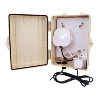
- Page 2 NP12-EER1 Installation Guide Page-1 Installing the eero Mesh Router The NP12-EER1 features a cradle type mount specifically designed to secure the eero Mesh Router inside the enclosure. 1. Slide the eero router into the mounting cradle as shown. eero Router Mounting Cradle 2.
- Page 3 NP12-EER1 Installation Guide Page-2 Connecting the eero Router A cable gland is provided on the enclosure to allow the Ethernet cable (not included) to be connected to the eero router. Cable Gland Pre-Wired Enclosure Cable Grommet (2) Used for Ethernet Power Cord Used for additional wiring Cable...
- Page 4 NP12-EER1 Installation Guide Page-3 5. Once the Ethernet cable is connected to the eero router, secure cable using the cable clamp provided on the enclosure. To prevent damaging the cable, do not over-tighten clamp. Cable Clamp 6. Connect the eero router’s power supply to the internal 120VAC power outlet. Secure any loose cables using the cable management straps provided in the accessory kit.
- Page 5 The enclosure can be secured to the wall using the mounting screws included in the kit. Install wall anchors as required. Mounting Tabs (3-Total) Mounting Screws sales@altelix.com Got Questions? We are here to help. USA & Canada: 866-660-9434 Contact us at:...
- Page 6 NP12-EER1 Installation Guide Page-5 Using Internal Mounting Feet 1. Using a ¼” drill bit, drill (4) holes through the center of the mounting feet in the locations shown. Inside of Enclosure (Equipment plate not shown for clarity) Mounting Feet Drill Locations Mounting the Enclosure 2.
- Page 7 NP12-EER1 Installation Guide Page-6 Mounting Hole Locations IS0204 Rev A 07/07/23...
- Page 8 Altelix LLC USA: 866-660-WIFI (9434) International: +1 561-660-9434 sales@altelix.com www.altelix.com Copyright (C) 2023 Altelix LLC. All rights reserved. Altelix and the Altelix logo are Trademarks and/or Registered Trademarks of Altelix LLC. Specifications are subject to change without notice. See www.altelix.com for most current information...
Need help?
Do you have a question about the NP12-EER1 Series and is the answer not in the manual?
Questions and answers