Chapters
Table of Contents
Troubleshooting

Related Manuals for Yamaha YZ250X 2023


Summary of Contents for Yamaha YZ250X 2023
- Page 1 2023 OWNER’S MANUAL MANUEL DU PROPRIÉTAIRE YZ250X Read this manual carefully before operating this vehicle. Il convient de lire attentivement ce manuel avant la première utilisation du véhicule. YZ250XP BRY-28199-70...
- Page 2 Read this manual carefully before operating this vehicle. This manual should stay with this vehicle if it is sold. Il convient de lire attentivement ce manuel avant la première utilisation du véhicule. Le manuel doit être remis avec le véhicule en cas de vente de ce dernier.
- Page 3 2023 OWNER’S MANUAL YZ250X Read this manual carefully before operating this vehicle. YZ250XP BRY-28199-70-E0...
- Page 4 If you believe that your vehicle has a defect which could cause a crash or could cause injury or death, you should immediately inform Transport Canada in addition to notifying Yamaha Motor Canada Ltd, Canada. If Transport Canada receives similar complaints, it may open an investigation, and if it finds that a safety defect exists in a group of vehicles, it may order a recall and remedy campaign.
- Page 5 EAM20080 YZ250XP OWNER’S MANUAL ©2023 by Yamaha Motor Co., Ltd. First edition, April 2022 All rights reserved. Any reprinting or unauthorized use without the written permission of Yamaha Motor Co., Ltd. is expressly prohibited. Printed in Japan.
- Page 6 EAM20180 IMPORTANT Congratulations on your purchase of a Yamaha YZ series. This model is the culmination of Yamaha’s vast experience in the production of pacesetting racing machines. It represents the highest grade of craftsmanship and reliability that have made Yamaha a leader.
-
Page 7: Table Of Contents
TABLE OF CONTENTS EAM10003 GENERAL INFORMATION SPECIFICATIONS PERIODIC CHECKS AND ADJUSTMENTS CHASSIS ENGINE ELECTRICAL SYSTEM TROUBLESHOOTING TUNING... -
Page 9: General Information
GENERAL INFORMATION SAFETY INFORMATION..................1-1 FOR SAFETY, BE SURE TO OBEY THE FOLLOWING: ......1-1 LOCATION OF IMPORTANT LABELS ............1-4 DESCRIPTION....................1-7 IDENTIFICATION....................1-8 VEHICLE IDENTIFICATION NUMBER ............1-8 ENGINE SERIAL NUMBER ...............1-8 INCLUDED PARTS...................1-9 NIPPLE WRENCH..................1-9 VALVE JOINT.....................1-9 SET PIN (tool for YPVS)................1-9 IMPORTANT INFORMATION .................1-10 PREPARATION FOR REMOVAL AND DISASSEMBLY......1-10 REPLACEMENT PARTS................1-10 INSTRUMENT AND CONTROL FUNCTIONS ..........1-11... -
Page 10: Safety Information
Yamaha ma- accidents. Many accidents have been chine, and take care to maintain it properly and caused by an automobile driver who did not operate it safely. - Page 11 1. Always wear an approved helmet. Yamaha can neither endorse nor recommend 2. Wear a face shield or goggles. Wind in your the use of accessories not sold by Yamaha or unprotected eyes could contribute to an im- modifications not specifically recommended by...
- Page 12 SAFETY INFORMATION Aftermarket Tires and Rims The tires and rims that came with your motorcy- cle were designed to match the performance ca- pabilities and to provide the best combination of handling, braking, and comfort. Other tires, rims, sizes, and combinations may not be appropriate. Refer to “CHECKING THE TIRES”...
-
Page 13: Location Of Important Labels
LOCATION OF IMPORTANT LABELS EAM20085 LOCATION OF IMPORTANT LABELS Please read the following important labels carefully before operating this vehicle. 1, 2, 3 4, 5 6, 7 8, 9... - Page 14 LOCATION OF IMPORTANT LABELS...
- Page 15 LOCATION OF IMPORTANT LABELS AUS, NZL, ZAF...
-
Page 16: Description
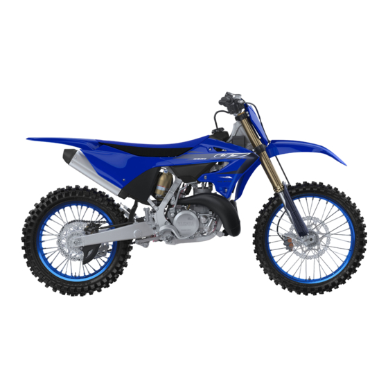
DESCRIPTION EAM20086 DESCRIPTION 13 14 15 11.Check bolt (Transmission oil level) 1. Clutch lever 12.Rear brake pedal 2. Engine stop switch 13.Valve joint 3. Front brake lever 14.Fuel cock 4. Throttle grip 15.Starter knob 5. Radiator cap 16.Drive chain 6. Fuel tank cap 17.Air filter 7. -
Page 17: Identification
There are two significant reasons for knowing the serial number of your vehicle: 1. When ordering parts, you can give the num- ber to your Yamaha dealer for positive identi- fication of the model you own. 2. If your vehicle is stolen, the authorities will need the number to search for and identify your vehicle. -
Page 18: Included Parts
INCLUDED PARTS EAM20088 INCLUDED PARTS EAM30005 NIPPLE WRENCH The nipple wrench “1” is used to tighten the spoke. EAM30534 VALVE JOINT This valve joint “1” prevents fuel from flowing out and is installed to the fuel tank breather hose. ECA27110 NOTICE In this installation, make sure the arrow fac- es the fuel tank and also downward. -
Page 19: Important Information
YAMAHA genuine Refer to “CARE” on page 1-18. parts and recommended parts. -
Page 20: Instrument And Control Functions
INSTRUMENT AND CONTROL FUNCTIONS EAM20181 INSTRUMENT AND CONTROL FUNCTIONS EAM30182 ENGINE STOP SWITCH The engine stop switch “1” is located on the left handlebar. Continue pushing the engine stop switch till the engine comes to a stop. EAM30188 FRONT BRAKE LEVER The front brake lever “1”... -
Page 21: Starter Knob (Choke)
INSTRUMENT AND CONTROL FUNCTIONS in this position. RES: With the lever in this position fuel flows to the carburetor from the reserve section of the fuel tank after the main supply of the fuel has been depleted. Normal riding is possible with the lever is in this position, but it is recommended to add fuel as soon as possible. -
Page 22: Starting And Break-In
STARTING AND BREAK-IN with firm stroke. EAM20123 STARTING AND BREAK-IN 4. Run the engine at idle or slightly higher until it warms up: this usually takes about one or two EAM30538 minutes. FUEL AND ENGINE MIXING OIL 5. The engine is warmed up when it responds Mix oil with the gas at the ratio specified below. - Page 23 STARTING AND BREAK-IN drive chain, looseness of the spoke, and so ECA25821 NOTICE After a break-in or after each race, always check the points shown in “TORQUE- CHECK POINTS” for tightening torques and retighten them. Also when the following parts are replaced, a break-in is required.
-
Page 24: Maintenance After Break-In
Disassemble the carburetor and clean the AIR FILTER MAINTENANCE small holes, blowing them with compressed Apply the Yamaha foam air filter oil or other qual- air. ity foam air filter oil to the element. (Excess oil in • CDI magneto... -
Page 25: Torque-Check Points
TORQUE-CHECK POINTS EAM20125 TORQUE-CHECK POINTS Frame construction Combined seat and fuel tank Fuel tank to frame Frame to rear frame Engine mounting Frame to engine Engine bracket to engine Engine bracket to frame Seat Seat to frame Steering Steering stem to handlebar Steering stem to frame Steering stem to upper bracket Upper bracket to handlebar... - Page 26 TORQUE-CHECK POINTS Plastic cover Tightening of front fender Tightening of fork leg protector Tightening of air scoop Left cover to rear frame Tightening of side cover Tightening of rear fender Tightening of mud flap Tightening of rear brake disc cover Tightening of rear brake caliper cover Concerning the tightening torque, refer to “TIGHTENING TORQUES”...
-
Page 27: Motorcycle Care And Storage
MOTORCYCLE CARE AND STORAGE ucts are used on hard-to-remove dirt, do EAM20126 MOTORCYCLE CARE AND STOR- not leave the cleaner on the affected area any longer than instructed. Also, thorough- ly rinse the area off with water, immediately dry it, and then apply a corrosion protec- EAM30200 CARE tion spray. -
Page 28: Storage
Salt sprayed on roads in the winter may remain well into spring. • Consult a Yamaha dealer for advice on what 1. Clean the motorcycle with cold water and a products to use. - Page 29 MOTORCYCLE CARE AND STORAGE stored. Long-term Before storing your motorcycle for several months: 1. Follow all the instructions in “CARE” on page 1-18. 2. Drain the fuel tank, fuel lines, and the carbu- retor float bowl. 3. Perform the following steps to protect the cyl- inder, piston rings, etc.
- Page 30 MOTORCYCLE CARE AND STORAGE 1-21...
-
Page 31: Specifications
SPECIFICATIONS GENERAL SPECIFICATIONS................2-1 ENGINE SPECIFICATIONS ................2-2 CHASSIS SPECIFICATIONS ................2-4 TIGHTENING TORQUES .................2-6 GENERAL TIGHTENING TORQUE SPECIFICATIONS......2-6 ENGINE TIGHTENING TORQUES............2-7 CHASSIS TIGHTENING TORQUES............2-9... -
Page 32: General Specifications
GENERAL SPECIFICATIONS EAM20127 GENERAL SPECIFICATIONS Model Model BRY1 (CAN) BRY3 (AUS, NZL) Dimensions Overall length 2185 mm (86.0 in) Overall width 825 mm (32.5 in) Overall height 1290 mm (50.8 in) Seat height 975 mm (38.4 in) Wheelbase 1485 mm (58.5 in) Ground clearance 360 mm (14.17 in) Weight... -
Page 33: Engine Specifications
ENGINE SPECIFICATIONS EAM20128 ENGINE SPECIFICATIONS Engine Combustion cycle 2-stroke Cooling system Liquid cooled Induction system Reed valve Displacement 249 cm³ Number of cylinders Single cylinder Bore stroke 66.4 72.0 mm (2.61 2.83 in) Compression ratio 7.9–9.4 : 1 Starting system Kickstarter Fuel... - Page 34 3.571 (50/14) Final drive Chain Air filter Air filter element Wet element Air filter oil grade Yamaha foam air filter oil or other quality foam air filter oil Carburetor Type quantity PWK38 1 ID mark BRY1 00 Main jet...
-
Page 35: Chassis Specifications
Fork spring free length limit 492.0 mm (19.37 in) Inner tube bending limit 0.2 mm (0.01 in) Recommended oil Yamaha Suspension Oil S1 Quantity (left) 480.0 cm³ (16.23 US oz, 16.93 Imp.oz) Quantity (right) 480.0 cm³ (16.23 US oz, 16.93 Imp.oz) - Page 36 CHASSIS SPECIFICATIONS Compression damping Adjusting system Mechanical adjustable type Unit for compression damping adjustment Click Adjustment value from the start position (Soft) Adjustment value from the start position (STD) Adjustment value from the start position (Hard) Rear suspension Type Swingarm (link suspension) Spring Coil spring Shock absorber...
-
Page 37: Tightening Torques
TIGHTENING TORQUES EAM20131 TIGHTENING TORQUES EAM30205 GENERAL TIGHTENING TORQUE SPECIFICATIONS This chart specifies tightening torques for stan- dard fasteners with a standard ISO thread pitch. Tightening torque specifications for special com- ponents or assemblies are provided for each chapter of this manual. To avoid warpage, tight- en multi-fastener assemblies in a crisscross pat- tern and progressive stages until the specified tightening torque is reached. - Page 38 TIGHTENING TORQUES EAM30203 ENGINE TIGHTENING TORQUES - marked portion shall be checked for torque tightening after break-in or before each race. Thread Item Q’ty Tightening torques Remarks size Spark plug M14S 20 N·m (2.0 kgf·m, 15 lb·ft) Cylinder head nut 25 N·m (2.5 kgf·m, 18 lb·ft) Cylinder head stud bolt 13 N·m (1.3 kgf·m, 9.6 lb·ft)
- Page 39 TIGHTENING TORQUES Thread Item Q’ty Tightening torques Remarks size Silencer bolt 12 N·m (1.2 kgf·m, 8.9 lb·ft) / Fiber bolt 10 N·m (1.0 kgf·m, 7.4 lb·ft) Crankcase bolt 14 N·m (1.4 kgf·m, 10 lb·ft) Crankcase cover screw (left) 5 N·m (0.5 kgf·m, 3.7 lb·ft) Drive sprocket cover screw 5 N·m (0.5 kgf·m, 3.7 lb·ft) Crankcase cover screw (right)
- Page 40 TIGHTENING TORQUES EAM30204 CHASSIS TIGHTENING TORQUES - marked portion shall be checked for torque tightening after break-in or before each race. Thread Item Q’ty Tightening torques Remarks size Upper bracket pinch bolt 21 N·m (2.1 kgf·m, 15 lb·ft) Lower bracket pinch bolt 21 N·m (2.1 kgf·m, 15 lb·ft) ...
- Page 41 TIGHTENING TORQUES Thread Item Q’ty Tightening torques Remarks size Front brake disc bolt 12 N·m (1.2 kgf·m, 8.9 lb·ft) / Rear brake disc bolt 12 N·m (1.2 kgf·m, 8.9 lb·ft) / Footrest bracket bolt 55 N·m (5.5 kgf·m, 41 lb·ft) Rear brake pedal bolt 26 N·m (2.6 kgf·m, 19 lb·ft) ...
- Page 42 TIGHTENING TORQUES Thread Item Q’ty Tightening torques Remarks size Fuel tank bolt 10 N·m (1.0 kgf·m, 7.4 lb·ft) Fuel cock screw 4.0 N·m (0.40 kgf·m, 3.0 lb·ft) Fuel tank screw (seat set side) 7 N·m (0.7 kgf·m, 5.2 lb·ft) Fuel tank bracket bolt 7 N·m (0.7 kgf·m, 5.2 lb·ft) Seat bolt...
-
Page 43: Periodic Checks And Adjustments
PERIODIC CHECKS AND ADJUSTMENTS MAINTENANCE INTERVALS................3-1 MAINTENANCE INTERVALS ..............3-1 PRE-OPERATION INSPECTION AND MAINTENANCE .........3-4 GENERAL INSPECTION AND MAINTENANCE........3-4 ENGINE ......................3-5 ADJUSTING THE PILOT AIR SCREW ............3-5 CHECKING THE ENGINE IDLING SPEED ..........3-5 CHECKING THE THROTTLE GRIP............3-5 CHECKING THE SPARK PLUG ..............3-5 CHECKING THE TRANSMISSION OIL LEVEL .........3-6 CHANGING THE TRANSMISSION OIL.............3-6 ADJUSTING THE CLUTCH LEVER FREE PLAY........3-7... - Page 44 LUBRICATING THE BRAKE LEVER ............3-24 LUBRICATING THE CLUTCH LEVER.............3-24 LUBRICATING THE PEDAL ..............3-24 CHECKING THE SIDESTAND..............3-24 LUBRICATING THE SIDESTAND............3-24...
-
Page 45: Maintenance Intervals
(e.g., rain, dirt, etc.). Therefore, earlier inspection is required by reference to the list below. Items marked with an asterisk should be performed by a Yamaha dealer as they require special tools, data and technical skills. - Page 46 • Replace. • Check chain slack, alignment and condition. • Adjust and thoroughly lubricate 16 * Drive chain chain with Yamaha chain and cable lube or equivalent. • Replace. • Check coolant level and for leak- ...
- Page 47 MAINTENANCE INTERVALS Every Every Every After race third race fifth race Item Routine break-in (about 2.5 (about 7.5 (about 12.5 required hours) hours) hours) • Check operation and for oil leak- age. • Adjust if necessary. • Clean dust seal and lubricate with lithium-soap-based grease.
-
Page 48: Pre-Operation Inspection And Maintenance
PRE-OPERATION INSPECTION AND MAINTENANCE EAM20134 PRE-OPERATION INSPECTION AND MAINTENANCE Before riding for break-in operation, practice or a race, make sure the machine is in good operating con- dition. Before using this machine, check the following points. EAM30209 GENERAL INSPECTION AND MAINTENANCE Item Inspect Page... -
Page 49: Engine
ENGINE gine idling speed should be adjusted. EAM20135 ENGINE 1. Check: • Throttle grip free play “a” EAM30607 ADJUSTING THE PILOT AIR SCREW Out of specification Regulate. 1. Adjust: Throttle grip free play • Pilot air screw “1” 3.0–5.0 mm (0.12–0.20 in) G088895 To optimize the fuel flow at a smaller throttle 2. -
Page 50: Checking The Transmission Oil Level
ENGINE into the cylinder. 3. Check: • Transmission oil level 3. Check: a. Remove the oil check bolt “1”. • Spark plug type b. Inspect the oil level. Incorrect Change. Manufacturer/model Be sure the machine is positioned straight up NGK/BR8EG when inspecting the oil level. -
Page 51: Adjusting The Clutch Lever Free Play
ENGINE G088887 2. Adjust: • Clutch lever free play Handlebar side a. Turn the adjuster “1” until the specified clutch lever free play is obtained. 5. Drain: • Transmission oil 6. Install: • Aluminum washer • Oil drain bolt Oil drain bolt 23 N·m (2.3 kgf·m, 17 lb·ft) If the clutch lever free play cannot be obtained on the handlebar side, use the adjuster on the... -
Page 52: Adjusting The Clutch Lever Position
4. Check: • Air filter element Damage Replace. 5. Apply: • Yamaha foam air filter oil or other quality foam air filter oil 2. Tighten: a. Put the air filter element into a plastic bag • Locknut and drip the filter oil into the bag. -
Page 53: Checking The Carburetor Joint
ENGINE worn. EAM30541 CHECKING THE CARBURETOR JOINT 1. Check: • Carburetor joint “1” Cracks/damage Replace. 7. Apply: • Lithium-soap-based grease (on the matching surface “a” on air filter ele- ment) EAM30542 CHECKING THE CARBURETOR HOSES The following procedure applies to all of the fuel and vacuum hoses. -
Page 54: Checking The Coolant Level
ENGINE Fiber bolt “1” Remove the inner pipe while holding the silencer 10 N·m (1.0 kgf·m, 7.4 lb·ft) in place with a vise etc. LOCTITE® Silencer bolt “2” 12 N·m (1.2 kgf·m, 8.9 lb·ft) LOCTITE® Side cover bolt (front side) 7 N·m (0.7 kgf·m, 5.2 lb·ft) Side cover bolt (rear side) 9 N·m (0.9 kgf·m, 6.6 lb·ft) -
Page 55: Checking The Cooling System
ENGINE Maximum level “a” or below Add coolant jury. When the engine has cooled, open the up to the maximum level. radiator cap as follows: Place a thick rag or a towel over the radiator cap and slowly turn the radiator cap counter- clockwise toward the detent to allow any re- sidual pressure to escape. - Page 56 ENGINE ly wash them with water and consult a doc- tor. • If coolant splashes on your clothes, quickly wash it away with water and then with soap and water. • If coolant is swallowed, induce vomiting and get immediate medical attention. ECA13481 NOTICE •...
-
Page 57: Chassis
CHASSIS air must be removed by bleeding the brake EAM20136 CHASSIS system. Air in the brake system will consid- erably reduce braking performance. EAM30479 ADJUSTING THE FRONT DISC BRAKE ECA13490 NOTICE There should be no free play at the brake lever After adjusting the brake lever position, end. -
Page 58: Checking The Brake Fluid Level
CHASSIS EWA19150 ECA13540 NOTICE WARNING A soft or spongy feeling in the brake pedal Brake fluid may damage painted surfaces can indicate the presence of air in the brake and plastic parts. Therefore, always clean up system. Before running, bleed the brake sys- any spilt brake fluid immediately. -
Page 59: Checking The Rear Brake Hose
CHASSIS 2. Check: the reservoir to overflow. • Brake hose clamp • Make sure that there is enough brake fluid be- Loose connection Tighten the clamp bolt. fore applying the brake. Ignoring this precau- 3. Stand the vehicle upright and apply the front tion could allow air to enter the brake system, brake several times. -
Page 60: Drive Chain Slack
CHASSIS h. Repeat steps (d) to (g) until all of the air bubbles have disappeared from the brake Measure drive chain slack between the drive fluid in the plastic hose. chain guide and the bottom of the chain as shown. During the procedure, keep adding brake fluid to the reservoir. -
Page 61: Lubricating The Drive Chain
CHASSIS Drive chain puller locknut 19 N·m (1.9 kgf·m, 14 lb·ft) EAM30251 LUBRICATING THE DRIVE CHAIN The drive chain consists of many interacting parts. If the drive chain is not maintained proper- ly, it will wear out quickly. Therefore, the drive chain should be serviced, especially when the vehicle is used in dusty areas. -
Page 62: Lubricating The Steering Head
If any damage is found or the front fork does not per and lower bearings. operate smoothly, have a Yamaha dealer check Refer to “STEERING HEAD” on page or repair it. 4-25. -
Page 63: Adjusting The Front Fork Legs
CHASSIS every run. ferences in production, the actual number of • Apply lithium-soap-based grease on the inner clicks always represents the entire adjusting tube. range. To obtain a precise adjustment, it would be advisable to check the number of clicks of each damping force adjusting mechanism and to modify the specifications as necessary. -
Page 64: Checking The Rear Shock Absorber Assembly
CHASSIS to modify the specifications as necessary. Refer to “REAR SHOCK ABSORBER AS- SEMBLY” on page 4-28. 3. Check: • Rear shock absorber assembly smooth ac- tion • Rear suspension link smooth action Sit astride the seat and shake your body up and down several times to check whether the rear shock absorber assembly operates smoothly. - Page 65 CHASSIS Direction “b” Direction “a” Spring preload is increased (suspen- Rebound damping is increased (sus- sion is harder). pension is harder). Direction “c” Direction “b” Spring preload is decreased (suspen- Rebound damping is decreased (sus- sion is softer). pension is softer). Spring preload adjusting positions Rebound damping Minimum...
-
Page 66: Checking The Swingarm Operation
CHASSIS Direction “a” Slow compression damping Compression damping is increased Minimum (soft) (suspension is harder). 20 click(s) in direction “b”* Direction “b” Standard Compression damping is decreased 8 click(s) in direction “b”* (suspension is softer). Maximum (hard) 0 click(s) in direction “b”* * With the adjusting screw fully turned in di- Fast compression damping rection “a”... -
Page 67: Checking And Tightening The Spokes
CHASSIS Tire air pressure (measured on cold tires) Front 100 kPa (1.00 kgf/cm², 15 psi) Rear 100 kPa (1.00 kgf/cm², 15 psi) • Check the tire while it is cold. G089060 • Because if the bead stopper tightening nut is loose when the tire pressure is low, the tire Spoke nipple wrench (6–7) could slip off the rim, thus be sure to check and... - Page 68 CHASSIS as soon as possible. Recommended lubricant 1. Check: Lithium-soap-based grease • Outer cable Damage Replace. 2. Check: • Cable operation Rough movement Lubricate. Recommended lubricant Engine oil or a suitable cable lu- bricant Hold the cable end upright and pour a few drops of lubricant into the cable sheath or use a suit- able lubricating device.
- Page 69 CHASSIS GENERAL CHASSIS..................4-1 REMOVING THE NUMBER PLATE............4-1 REMOVING THE SIDE COVER..............4-1 FRONT WHEEL....................4-2 REMOVING THE FRONT WHEEL.............4-2 INSTALLING THE FRONT WHEEL ............4-2 REAR WHEEL ....................4-3 REMOVING THE REAR WHEEL ...............4-3 CHECKING AND REPLACING THE REAR WHEEL SPROCKET ....4-3 INSTALLING THE REAR WHEEL..............4-3 FRONT BRAKE ....................4-5 REPLACING THE FRONT BRAKE PADS ..........4-5 REAR BRAKE ....................4-7...
- Page 70 CHECKING THE DRIVE CHAIN ..............4-30 CHECKING THE DRIVE SPROCKET............4-31 CHECKING THE REAR WHEEL SPROCKET.........4-31 INSTALLING THE DRIVE CHAIN ............4-31...
-
Page 71: General Chassis
GENERAL CHASSIS EAM20094 GENERAL CHASSIS EAM30371 REMOVING THE NUMBER PLATE 1. Remove: • Number plate bolt • Number plate “1” • The projection “a” is inserted into the band of the number plate. Pull the band off the projec- tion before removal. •... -
Page 72: Front Wheel
FRONT WHEEL EAM20095 ECA24430 FRONT WHEEL NOTICE Before tightening the front wheel axle nut, EAM30017 push down hard on the handlebar(s) several REMOVING THE FRONT WHEEL times and check if the front fork rebounds 1. Use a maintenance stand to raise the front smoothly. -
Page 73: Rear Wheel
REAR WHEEL EAM20096 REAR WHEEL EAM30022 REMOVING THE REAR WHEEL 1. Use a maintenance stand to raise the rear wheel off the ground. EWA13120 WARNING Securely support the vehicle so that there is no danger of it falling over. G088904 b. - Page 74 REAR WHEEL Refer to “DRIVE CHAIN SLACK” on page 3-16. 3. Install: • Drive chain puller (left) “1” 6. Tighten: • Rear wheel axle “2” • Rear wheel axle nut “1” • Install the drive chain puller (left), and insert the Rear wheel axle nut rear wheel axle from the left side.
-
Page 75: Front Brake
FRONT BRAKE EAM20097 FRONT BRAKE Brake pad lining thickness limit 1.0 mm (0.04 in) EAM30519 REPLACING THE FRONT BRAKE PADS When replacing the brake pads, it is not neces- sary to disconnect the brake hose or disassem- ble the brake caliper. 1. - Page 76 FRONT BRAKE e. Install the brake caliper “4” and tighten the pad pin “5”. Front brake caliper bolt 28 N·m (2.8 kgf·m, 21 lb·ft) Brake pad pin 17 N·m (1.7 kgf·m, 13 lb·ft) f. Install the pad pin plug “6”. Brake pad pin plug 2.5 N·m (0.25 kgf·m, 1.8 lb·ft) 4.
-
Page 77: Rear Brake
REAR BRAKE EAM20098 REAR BRAKE Brake pad lining thickness limit 1.0 mm (0.04 in) EAM30523 REPLACING THE REAR BRAKE PADS When replacing the brake pads, it is not neces- sary to disconnect the brake hose or disassem- ble the brake caliper. 1. - Page 78 REAR BRAKE Refer to “BLEEDING THE HYDRAULIC BRAKE SYSTEM” on page 3-15. e. Install the brake caliper “5” and the rear wheel “6”. f. Tighten the pad pin “7”. Brake pad pin 17 N·m (1.7 kgf·m, 13 lb·ft) g. Install the pad pin plug “8” and the protector “9”.
-
Page 79: Handlebar
HANDLEBAR EAM20099 EAM30054 HANDLEBAR INSTALLING THE HANDLEBAR 1. Stand the vehicle upright on a level surface. EAM30052 EWA13120 REMOVING THE HANDLEBAR WARNING 1. Stand the vehicle upright on a level surface. Securely support the vehicle so that there is EWA13120 no danger of it falling over. - Page 80 HANDLEBAR stalled with the punch marks “a” facing for- 4. Tighten: ward. • Lower handlebar holder nut “1” • Install the handlebar so that the marks “b” are Lower handlebar holder nut in place on both sides. 40 N·m (4.0 kgf·m, 30 lb·ft) •...
- Page 81 HANDLEBAR clamp should be installed according to the di- the slot “c” in the tube guide. mensions shown. • Pass the engine stop switch lead in the middle of the clutch lever holder. 0 mm (0 in) 0 mm (0 in) 10.Install: •...
- Page 82 HANDLEBAR Throttle cable cap screw 0.5 N·m (0.05 kgf·m, 0.37 lb·ft) 12.Install: • Throttle cable “1” (to the tube guide “2”) 15.Adjust: Apply the lithium-soap-based grease on the • Throttle grip free play throttle cable end and tube guide cable winding Refer to “CHECKING THE THROTTLE portion.
- Page 83 HANDLEBAR 18.Install: • Grip cap bolt “1” Grip cap bolt 3.8 N·m (0.38 kgf·m, 2.8 lb·ft) EWA21080 WARNING After tightening the bolts, check that the throttle grip “2” moves smoothly. If it does not, retighten the bolts for adjustment. 4-13...
-
Page 84: Front Fork
FRONT FORK EAM20100 FRONT FORK • While compressing the inner tube “2”, set the cap bolt ring wrench “4” between the inner tube EAM30055 and locknut “3”. REMOVING THE FRONT FORK LEGS • Hold the locknut and remove the adjuster. 1. -
Page 85: Checking The Front Fork Legs
FRONT FORK dial gauge reading. EWA13650 WARNING Do not attempt to straighten a bent inner tube as this may dangerously weaken it. 2. Check: • Outer tube Scratches/wear/damage Replace. 3. Measure: • Fork spring free length “a” 5. Remove: Out of specification ... -
Page 86: Assembling The Front Fork Legs
1. Stretch the damper assembly fully. 2. Fill: • Damper assembly Recommended oil Yamaha Suspension Oil S1 Standard oil amount 7. Check: 205 cm³ (6.93 US oz, 7.21 Imp.oz) • Adjuster “1”... - Page 87 FRONT FORK 4. Measure: 6. Loosen: • Oil level (left and right) “a” • Compression damping force adjuster “1” Out of specification Regulate. • Before loosening the damping force adjuster, Standard oil level record the setting position. 145–148 mm (5.71–5.83 in) •...
- Page 88 FRONT FORK 9. Tighten: • Base valve “1” Base valve (front fork) 28 N·m (2.8 kgf·m, 21 lb·ft) Hold the damper assembly with the cap bolt ring wrench “2” and use the cap bolt wrench “3” to tighten the base valve. Cap bolt wrench 12.Allow the overflowing oil to escape at the hole 90890-01500...
- Page 89 FRONT FORK • Apply the lithium-soap-based grease on the dust seal lip and oil seal lip. • Apply the fork oil on the inner tube. • Install the scraper to the inner tube as shown in the illustration. • When installing the oil seal, use vinyl seat with fork oil applied to protect the oil seal lip.
- Page 90 FRONT FORK G088924 19.Install: 22.Measure: • Stopper ring “1” • Distance “a” Out of specification Turn the locknut to Fit the stopper ring correctly in the groove in the specification. outer tube. Distance “a” 16 mm (0.63 in) or more Between the damper assembly “1”...
- Page 91 FRONT FORK ECA24560 NOTICE Allow the damper assembly to slide slowly down the inner tube until it contacts the bot- tom of the inner tube. Be careful not to dam- age the inner tube. 27.Measure: • Gap “a” between the adjuster “1” and the locknut “2”...
-
Page 92: Installing The Front Fork Legs
55 N·m (5.5 kgf·m, 41 lb·ft) LOCTITE® 32.Install: • Protector guide “1” 30.Fill: • Front fork leg Recommended oil Yamaha Suspension Oil S1 Standard oil amount 285 cm³ (9.6 US oz, 10.1 Imp.oz) EAM30059 INSTALLING THE FRONT FORK LEGS Extent of adjustment 1. Install: 265–365 cm³... - Page 93 FRONT FORK Cap bolt ring wrench 90890-01501 Cap bolt ring wrench YM-01501 5. Install: • Protector “1” • Front fork protector bolt “2” Front fork protector bolt 5 N·m (0.5 kgf·m, 3.7 lb·ft) 3. Adjust: • Front fork top end “a” Front fork top end (standard) “a”...
- Page 94 FRONT FORK 4-24...
-
Page 95: Steering Head
STEERING HEAD c. Install a new bearing race. EAM20101 STEERING HEAD ECA14270 NOTICE EAM30060 If the bearing race is not installed properly, REMOVING THE LOWER BRACKET the steering head pipe could be damaged. 1. Use a maintenance stand to raise the front wheel off the ground. - Page 96 STEERING HEAD 2. Install: • Bearing race • Upper bearing “1” • Bearing race cover “2” Apply the lithium-soap-based grease on the bearing and bearing race cover lip. 5. Check the steering stem by turning this lock to lock. If there is any binding, remove the steering stem and check the steering bear- ing.
- Page 97 STEERING HEAD Upper bracket pinch bolt 21 N·m (2.1 kgf·m, 15 lb·ft) • Lower bracket pinch bolt “2” Lower bracket pinch bolt 21 N·m (2.1 kgf·m, 15 lb·ft) EWA19330 WARNING Tighten the lower bracket to specified 8. Install: torque. If torqued too much, it may cause the •...
-
Page 98: Rear Shock Absorber Assembly
REAR SHOCK ABSORBER ASSEMBLY EAM20102 REAR SHOCK ABSORBER AS- SEMBLY EAM30065 REMOVING THE REAR SHOCK ABSORBER ASSEMBLY 1. Use a maintenance stand to raise the rear wheel off the ground. EWA13120 WARNING Securely support the vehicle so that there is no danger of it falling over. -
Page 99: Swingarm
SWINGARM EAM20103 SWINGARM EAM30071 REMOVING THE SWINGARM 1. Use a maintenance stand to raise the rear wheel off the ground. EWA13120 WARNING Securely support the vehicle so that there is no danger of it falling over. 2. Measure: • Swingarm side play •... -
Page 100: Chain Drive
CHAIN DRIVE EAM20104 CHAIN DRIVE EAM30075 REMOVING THE DRIVE CHAIN 1. Stand the vehicle on a level surface. EWA13120 WARNING Securely support the vehicle so that there is no danger of it falling over. G088938 Place the vehicle on a maintenance stand so •... - Page 101 CHAIN DRIVE G088940 G088904 b. Correct 1. Drive chain roller 2. Drive sprocket EAM30078 CHECKING THE REAR WHEEL SPROCKET Refer to “CHECKING AND REPLACING THE REAR WHEEL SPROCKET” on page 4-3. EAM30079 G088941 INSTALLING THE DRIVE CHAIN 4. Check: 1. Install: •...
- Page 102 CHAIN DRIVE ECA24590 NOTICE A drive chain that is too tight will overload the engine and other vital parts, and one that is too loose can skip and damage the swing- arm or cause an accident. Therefore, keep the drive chain slack within the specified lim- its.
-
Page 103: Engine
ENGINE CLUTCH ......................5-1 REMOVING THE CLUTCH ................5-1 CHECKING THE FRICTION PLATES............5-1 CHECKING THE CLUTCH PLATES ............5-1 CHECKING THE CLUTCH SPRINGS............5-1 CHECKING THE CLUTCH HOUSING ............5-1 CHECKING THE CLUTCH BOSS..............5-2 CHECKING THE PRESSURE PLATE ............5-2 CHECKING THE PUSH LEVER SHAFT............5-2 CHECKING THE PUSH RODS ..............5-2 CHECKING THE PRIMARY DRIVE GEAR..........5-2 CHECKING THE PRIMARY DRIVEN GEAR ..........5-2 INSTALLING THE CLUTCH...............5-2... - Page 104 CLUTCH EAM20111 EAM30110 CLUTCH CHECKING THE CLUTCH PLATES 1. Check: • Clutch plate EAM30108 REMOVING THE CLUTCH Damage Replace the clutch plates as a 1. Remove: set. • Clutch boss nut “1” 2. Measure: • Lock washer • Clutch plate warpage •...
- Page 105 CLUTCH EAM30484 CHECKING THE PUSH RODS 1. Check: • Push rod 1 “1” • Bearing “2” • Washer “3” • Push rod 2 “4” Cracks/damage/wear Replace. G088994 EAM30113 CHECKING THE CLUTCH BOSS 1. Check: • Clutch boss splines Damage/pitting/wear Replace the clutch boss.
- Page 106 CLUTCH • Push lever shaft “3” • Copper washer “4” • Push lever shaft bolt “5” Push lever shaft bolt 6 N·m (0.6 kgf·m, 4.4 lb·ft) Apply the lithium-soap-based grease on the oil seal lip. 4. Install: • Lock washer “1” •...
- Page 107 CLUTCH plate and ending with a friction plate. • Install the friction plates that have black paint on the outer circumference of the pawls at the innermost and outermost positions, respec- tively. • Apply the transmission oil on the friction plates and clutch plates.
- Page 108 CLUTCH Tighten the bolts in stage, using a crisscross pat- tern. 13.Install: • O-ring “1” • Clutch cable “2” Apply the lithium-soap-based grease on the O- ring.
-
Page 109: Electrical System
ELECTRICAL SYSTEM WIRING DIAGRAM...................6-1 COLOR CODE ...................6-1... - Page 110 WIRING DIAGRAM EAM20195 WIRING DIAGRAM 1. CDI unit 2. Engine stop switch 3. Ignition coil 4. Throttle position sensor 5. Solenoid valve 6. Neutral switch 7. CDI magneto 8. Spark plug EAM30608 COLOR CODE Black Blue Orange Sky blue Yellow Black/Blue Black/Red Black/White...
-
Page 111: Troubleshooting
TROUBLESHOOTING TROUBLESHOOTING..................7-1 GENERAL INFORMATION ................7-1 TROUBLESHOOTING OF ENGINE............7-1 TROUBLESHOOTING OF CLUTCH............7-6 TROUBLESHOOTING OF TRANSMISSION ..........7-7 TROUBLESHOOTING OF COOLING SYSTEM ........7-8 TROUBLESHOOTING OF BRAKE ............7-9 TROUBLESHOOTING OF SUSPENSION..........7-9 TROUBLESHOOTING OF STEERING/HANDLING ........7-11... -
Page 112: Troubleshooting
• The following guide for troubleshooting represent quick and easy procedures for checking these vital systems yourself. However, should your motorcycle require any repair, take it to a Yamaha dealer, whose skilled technicians have the necessary tools, experience, and know-how to service the motor- cycle properly. - Page 113 TROUBLESHOOTING Symptom Possible cause Actions Measure the compression pres- — sure. Tighten the spark plugs to the Loose spark plug specified torque. Tighten bolts or nuts on cylinder Loose cylinder head or cylinder head and cylinder to the specified torque. Compression pressure is low Damaged cylinder head gasket Replace the cylinder head gasket.
- Page 114 TROUBLESHOOTING Symptom Possible cause Actions Damaged or worn needle valve Replace the needle valve. Adjust the fuel level to the proper Incorrect fuel level level. Bent, worn, or damaged starter Replace the starter plunger. plunger Incorrectly adjusted starter cable Adjust the starter cable. Clogged or damaged carburetor Clean, repair, or replace the car- breather hose...
- Page 115 TROUBLESHOOTING Symptom Possible cause Actions Water or foreign material in fuel, Change fuel. degraded fuel Clogged carburetor air passage Clean the carburetor. Incorrectly adjusted throttle cable Adjust the throttle grip free play. Improperly synchronized carbure- Adjust synchronization of carbure- tors tors.
- Page 116 TROUBLESHOOTING Symptom Possible cause Actions Check the air induction system. Failed air induction system Repair or replace faulty parts. Clogged vacuum hose Clean the vacuum hose. Cracks and damage in vacuum Replace the vacuum hose. hose — Damaged carburetor joint Replace the carburetor joint.
-
Page 117: Troubleshooting Of Clutch
TROUBLESHOOTING EAM30510 TROUBLESHOOTING OF CLUTCH Manual clutch Symptom Possible cause Actions Improperly assembled clutch Reassemble the clutch. Improperly adjusted clutch cable Adjust the clutch lever free play. Tighten the clutch spring bolts to Loose clutch spring the specified torque. Replace the clutch springs as a Fatigued clutch spring set. -
Page 118: Troubleshooting Of Transmission
TROUBLESHOOTING Symptom Possible cause Actions Replace the primary drive gear or Damaged or worn primary driven crankshaft, and the clutch housing gear as a set. Tighten the clutch boss nut to the Loose clutch boss nut specified torque. Clutch noise Fatigued clutch damper Replace the clutch housing. -
Page 119: Troubleshooting Of Cooling System
TROUBLESHOOTING EAM30512 TROUBLESHOOTING OF COOLING SYSTEM Symptom Possible cause Actions Carbon buildup in piston head and Clean the piston head and com- combustion chamber bustion chamber. Clogged engine cooling water Check and clean the engine cool- passages ing water passages. Damaged or leaking radiator Replace the radiator. -
Page 120: Troubleshooting Of Brake
TROUBLESHOOTING EAM30513 TROUBLESHOOTING OF BRAKE Symptom Possible cause Actions Worn brake pad Replace the brake pads as a set. Worn or deflected brake disc Replace the brake disc. Air in hydraulic brake system Bleed the hydraulic brake system. Check the hydraulic brake system Brake fluid leakage and repair or replace faulty parts as necessary. - Page 121 TROUBLESHOOTING Symptom Possible cause Actions Fatigued or broken fork spring Replace the fork spring. Incorrect oil viscosity (low) Change to recommended fork oil. Incorrect oil level (low) Adjust to the specified oil level. Improperly adjusted spring pre- Adjust the spring preload. Front fork is soft load (soft) Improperly adjusted rebound...
-
Page 122: Troubleshooting Of Steering/Handling
TROUBLESHOOTING Symptom Possible cause Actions Oil leaking from rear shock Replace the rear shock absorber. absorber Gas leaking from rear shock Replace the rear shock absorber. absorber Fatigued or damaged rear shock Replace the rear shock absorber. absorber spring Rear suspension is soft Improperly adjusted rear shock Adjust the spring preload. - Page 123 TROUBLESHOOTING Symptom Possible cause Actions Tighten the spoke and adjust the Loose spoke runout. Damaged or worn wheel bearing Replace the wheel bearing. Worn, deformed, or incorrect tire Replace the tire. Tighten the wheel axle nut to the Loose wheel axle nut Rear wheel vibration specified torque.
- Page 124 TROUBLESHOOTING 7-13...
-
Page 125: Tuning
TUNING ENGINE ......................8-1 CARBURETOR SETTING................8-1 ATMOSPHERIC CONDITIONS AND CARBURETOR SETTINGS ....8-1 TEST RUN....................8-1 EFFECTS OF THE SETTING PARTS ON THE THROTTLE VALVE OPENING ....................8-2 MAIN JET ADJUSTMENT ................8-2 ADJUSTING THE POWER JET ..............8-2 PILOT AIR SCREW ADJUSTMENT............8-2 PILOT JET ADJUSTMENT.................8-3 JET NEEDLE ADJUSTMENT..............8-3 JET NEEDLE GROOVE POSITION ADJUSTMENT........8-4 RELATIONSHIP WITH THROTTLE OPENING .........8-4... -
Page 126: Engine
ENGINE • Lower atmospheric pressure (at a high alti- EAM20198 ENGINE tude) reduces the density of the air. EAM30590 EAM30592 CARBURETOR SETTING TEST RUN • The role of fuel is to cool the engine, and in the After warming up the engine equipped with the case of a 2-stroke engine, to lubricate the en- standard type carburetor(s) and spark plug(s), gine in addition to power generation. -
Page 127: Effects Of The Setting Parts On The Throttle Valve Opening
ENGINE EAM30593 EFFECTS OF THE SETTING PARTS ON THE THROTTLE VALVE OPENING EAM30604 ADJUSTING THE POWER JET The richness of air-fuel mixture under 8500 r/min to the extent of 1/2 to full opened throttle can be set by changing the power jet “1”. A larger size jet results in a richer mixture, and a smaller size in a leaner mixture. -
Page 128: Pilot Jet Adjustment
ENGINE EAM30596 PILOT JET ADJUSTMENT The richness of air-fuel mixture with the throttle fully closed to 1/2 open can be set by turning the pilot jet “1”. It is changed when adjustment can- NYHG not be made by the pilot air screw alone. NYHH A larger size jet results in a richer mixture at low NYHW... -
Page 129: Jet Needle Groove Position Adjustment
ENGINE EAM30605 RELATIONSHIP WITH THROTTLE OPENING The flow of the fuel through the carburetor main system is controlled by the main jet and then, it is further regulated by the area between the main nozzle and the jet needle. On the relation- ship between the fuel flow and the throttle open- ing, the fuel flow relates to the jet needle straight portion diameter around 1/8 to 1/4 throttle open-... -
Page 130: Carburetor Setting Parts
ENGINE EAM30599 Part name Size Part number CARBURETOR SETTING PARTS Jet needle Rich N3CG 4SR-14916-CG Part name Size Part number “3” N3EG 4SR-14916-EG Main jet “1” Rich #190 4MX-14943-45 NYHG BRY-14916-HG #188 4MX-14943-95 N8RH 4SR-14916-RH #185 4MX-14943-44 N3EH 4SR-14916-EH #182 4MX-14943-94 N3CH 4SR-14916-CH... - Page 131 ENGINE...
-
Page 132: Road Condition And Examples Of Carburetor Setting
ENGINE EAM30601 ROAD CONDITION AND EXAMPLES OF CARBURETOR SETTING General condition Sandy condition 15–25 C 15–25 C Under 10 C Over 25 C Under 10 C Over 25 C (59–77 F) (59–77 F) (50 F) (77 F) (50 F) (77 F) (Spring, (Spring, (Winter) - Page 133 ENGINE Symptom Setting Checking • Closed to 1/4 throttle Use jet needle having a smaller diam- *Hard breathing eter. Speed down • Closed to 1/4 throttle Use jet needle with a larger diameter. Poor acceleration White smoke • Unstable at low speeds Lower jet needle clip position.
-
Page 134: Change Of The Heat Range Of Spark Plugs
ENGINE EAM30603 CHANGE OF THE HEAT RANGE OF SPARK PLUGS Judging from the discoloration of spark plugs, if they are found improper, it can be corrected by the following two methods; changing carburetor settings and changing the heat range of spark plug. -
Page 135: Chassis
CHASSIS EAM20119 EAM30169 CHASSIS DRIVE AND REAR WHEEL SPROCKETS SETTING PARTS EAM30168 SELECTION OF THE SECONDARY Part name Type Part number REDUCTION RATIO (SPROCKET) Drive 9383E-13216 sprocket “1” Secondary reduction ratio = Number of (STD) 9383E-14215 rear wheel sprocket teeth/Number of Rear wheel 17D-25447-50 drive sprocket teeth... -
Page 136: Front Fork Setting
• Change the compression damping force. Turn in one or two clicks. Recommended oil Yamaha Suspension Oil S1 Generally a soft spring gives a soft riding feeling. Standard oil amount 285 cm³ (9.6 US oz, 10.1 Imp.oz) Rebound damping tends to become stronger... -
Page 137: Front Fork Setting Parts
CHASSIS put the rear wheel above the floor, and mea- sure the length “a” between the rear wheel Generally a stiff spring gives a stiff riding feeling. Rebound damping tends to become weaker, re- axle center and “” mark of rear fender. sulting in lack of a sense of contact with the road surface or in a vibrating handlebar. -
Page 138: Setting Of Spring After Replacement
CHASSIS EAM30177 EAM30178 SETTING OF SPRING AFTER REAR SHOCK ABSORBER SETTING PARTS REPLACEMENT • Rear shock spring “1” After replacement, be sure to adjust the spring to [Equal-pitch steel spring] the set length [sunken length 90–100 mm (3.5– STD spring rate 3.9 in)] and set it. - Page 139 CHASSIS • Spring preload adjusting positions [Unequal-pitch steel spring] Spring Spring preload adjusting positions I.D. Type rate Part number Minimum mark/Q’ty (N/mm) Position in which the spring is turned in 1.5 mm (0.06 in) from 5UN-22212-A0 SOFT Green/2 (Silver) its free length. Standard 5UN-22212-B0 Red/2...
-
Page 140: Suspension Setting (Front Fork)
CHASSIS EAM30179 SUSPENSION SETTING (FRONT FORK) • If any of the following symptoms is experienced with the standard position as the base, make resetting by reference to the adjustment procedure given in the same chart. • Before any change, set the rear shock absorber sunken length to the standard figure 90–100 mm (3.5–3.9 in). -
Page 141: Suspension Setting (Rear Shock Absorber)
CHASSIS Section Symptom Check Adjust Large Medium Small Jump Compression Turn adjuster clockwise (about 2 damping force clicks) to increase damping. Turn adjuster counterclockwise Rebound damp- (about 2 clicks) to decrease ing force damping. Low front, tend- ing to lower front Set sunken length for 95–100 posture Balance with rear... - Page 142 CHASSIS Section Symptom Check Adjust Large Medium Small Jump Turn adjuster counterclockwise Rebound damp- (about 2 clicks) to decrease Heavy and drag- ing force damping. ging Spring Replace with soft spring. Turn adjuster counterclockwise Rebound damp- (about 2 clicks) to decrease ing force damping.
- Page 144 PRINTED IN JAPAN...
- Page 146 PRINTED IN JAPAN 2022.05-0.1×1 ! (E, F)
Need help?
Do you have a question about the YZ250X 2023 and is the answer not in the manual?
Questions and answers