
Related Manuals for Yamaha YZ250 2021


Summary of Contents for Yamaha YZ250 2021
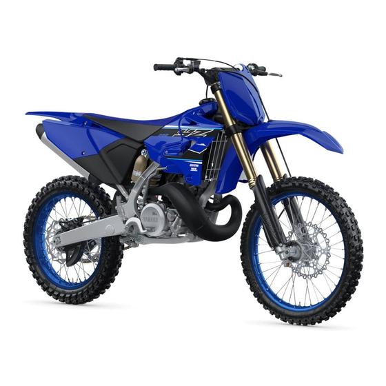
- Page 1 2021 OWNER’S MANUAL YZ250 YZ250X Read this manual carefully before operating this vehicle. YZ250M2 YZ250XM LIT-11626-34-11 BF1-28199-10...
- Page 2 Operating, servicing and maintaining a passenger vehicle or off-road vehicle can expose you to chemicals including engine exhaust, carbon monoxide, phthalates, and lead, which are known to the State of California to cause cancer and birth defects or other reproductive harm. To minimize exposure, avoid breathing exhaust, do not idle the engine except as necessary, service your vehicle in a well-ventilated area and wear gloves or wash your...
- Page 3 EAM20080 YZ250M2 YZ250XM OWNER’S MANUAL ©2021 by Yamaha Motor Corporation, U.S.A. First edition, April 2020 All rights reserved. Any reprinting or unauthorized use without the written permission of Yamaha Motor Corporation, U.S.A. is expressly prohibited. P/N. LIT-11626-34-11 Printed in Japan.
- Page 4 EAM20180 IMPORTANT Congratulations on your purchase of a Yamaha YZ series. This model is the culmination of Yamaha’s vast experience in the production of pacesetting racing machines. It represents the highest grade of craftsmanship and reliability that have made Yamaha a leader.
- Page 5 EAM20162 YAMAHA MOTOR CORPORATION, U.S.A. YZ MOTORCYCLE LIMITED WARRANTY...
-
Page 7: Table Of Contents
TABLE OF CONTENTS EAM10003 GENERAL INFORMATION SPECIFICATIONS PERIODIC CHECKS AND ADJUSTMENTS CHASSIS ENGINE ELECTRICAL SYSTEM TROUBLESHOOTING TUNING... - Page 9 GENERAL INFORMATION SAFETY INFORMATION ..................1-1 FOR SAFETY, BE SURE TO OBEY THE FOLLOWING:......1-1 LOCATION OF IMPORTANT LABELS.............1-4 DESCRIPTION....................1-5 IDENTIFICATION ....................1-6 VEHICLE IDENTIFICATION NUMBER ............1-6 ENGINE SERIAL NUMBER................1-6 INCLUDED PARTS ...................1-7 SIDESTAND (for YZ250) ................1-7 NIPPLE WRENCH ..................1-7 VALVE JOINT .....................1-7 SET PIN......................1-7 IMPORTANT INFORMATION ................1-8 PREPARATION FOR REMOVAL AND DISASSEMBLY ......1-8...
- Page 10 MOTORCYCLE CARE AND STORAGE............1-16 CARE ......................1-16 STORAGE ....................1-17...
-
Page 11: Safety Information
Yamaha ma- accidents. Many accidents have been chine, and take care to maintain it properly and caused by an automobile driver who did not operate it safely. - Page 12 1. Always wear an approved helmet. Yamaha can neither endorse nor recommend 2. Wear a face shield or goggles. Wind in your the use of accessories not sold by Yamaha or unprotected eyes could contribute to an im- modifications not specifically recommended by...
- Page 13 SAFETY INFORMATION Aftermarket Tires and Rims The tires and rims that came with your motorcy- cle were designed to match the performance ca- pabilities and to provide the best combination of handling, braking, and comfort. Other tires, rims, sizes, and combinations may not be appropriate. Refer to “CHECKING THE TIRES”...
-
Page 14: Location Of Important Labels
LOCATION OF IMPORTANT LABELS EAM20085 LOCATION OF IMPORTANT LABELS Please read the following important labels carefully before operating this vehicle. -
Page 15: Description
DESCRIPTION EAM20086 DESCRIPTION 11.Check bolt (Transmission oil level) 1. Clutch lever 12.Rear brake pedal 2. Engine stop switch 13.Valve joint 3. Front brake lever 4. Throttle grip 14.Fuel cock 15.Starter knob 5. Radiator cap 6. Fuel tank cap 16.Drive chain 17.Air filter 7. -
Page 16: Identification
There are two significant reasons for knowing the serial number of your vehicle: 1. When ordering parts, you can give the num- ber to your Yamaha dealer for positive identi- fication of the model you own. 2. If your vehicle is stolen, the authorities will need the number to search for and identify your vehicle. -
Page 17: Included Parts
INCLUDED PARTS EAM20088 INCLUDED PARTS EAM30372 SIDESTAND (for YZ250) This sidestand “1” is used to support only the machine when standing or transporting it. EWA20260 WARNING • Never apply additional force to the sides- tand. • Remove this sidestand before starting out. EAM30535 SET PIN This set pin “1”... -
Page 18: Important Information
YAMAHA genuine Refer to “CARE” on page 1-16. parts and recommended parts. -
Page 19: Instrument And Control Functions
INSTRUMENT AND CONTROL FUNCTIONS EAM20181 INSTRUMENT AND CONTROL FUNCTIONS EAM30182 ENGINE STOP SWITCH The engine stop switch “1” is located on the left handlebar. Continue pushing the engine stop switch till the engine comes to a stop. EAM30188 FRONT BRAKE LEVER The front brake lever “1”... -
Page 20: Fuel Cock (For Yz250X)
INSTRUMENT AND CONTROL FUNCTIONS in this position. EAM30190 SIDESTAND (for YZ250X) EAM30537 FUEL COCK (for YZ250X) This sidestand “1” is used to support only the The fuel cock supplies fuel from the tank to car- machine when standing or transporting it. buretor and also filters the fuel. -
Page 21: Starting And Break-In
STARTING AND BREAK-IN engine by kicking the kickstarter forcefully EAM20123 STARTING AND BREAK-IN with firm stroke. 4. Run the engine at idle or slightly higher until it EAM30538 warms up: this usually takes about one or two FUEL AND ENGINE MIXING OIL minutes. - Page 22 STARTING AND BREAK-IN of cables, free play of the brake, stretch of the drive chain, looseness of the spoke, and so ECA25821 NOTICE After a break-in or after each race, always check the points shown in “TORQUE- CHECK POINTS” for tightening torques and retighten them.
-
Page 23: Maintenance After Break-In
Disassemble the carburetor and clean the AIR FILTER MAINTENANCE small holes, blowing them with compressed Apply the Yamaha foam air filter oil or other qual- air. ity foam air filter oil to the element. (Excess oil in • CDI magneto... -
Page 24: Torque-Check Points
TORQUE-CHECK POINTS EAM20125 TORQUE-CHECK POINTS Frame construction Frame to rear frame Combined seat and fuel tank Fuel tank to frame Engine mounting Frame to engine Engine bracket to engine Engine bracket to frame Seat Seat to frame Steering Steering stem to handlebar Steering stem to frame Steering stem to upper bracket Upper bracket to handlebar... - Page 25 TORQUE-CHECK POINTS Plastic cover Tightening of front fender Tightening of fork leg protector Tightening of air scoop Left cover to rear frame Tightening of side cover Tightening of rear fender Tightening of mud flap Tightening of rear brake disc cover Tightening of rear brake caliper cover Concerning the tightening torque, refer to “TIGHTENING TORQUES”...
- Page 26 MOTORCYCLE CARE AND STORAGE ucts are used on hard-to-remove dirt, do EAM20126 MOTORCYCLE CARE AND STOR- not leave the cleaner on the affected area any longer than instructed. Also, thorough- ly rinse the area off with water, immediately dry it, and then apply a corrosion protec- EAM30200 CARE tion spray.
- Page 27 Salt sprayed on roads in the winter may remain well into spring. • Consult a Yamaha dealer for advice on what 1. Clean the motorcycle with cold water and a products to use.
- Page 28 MOTORCYCLE CARE AND STORAGE stored. Long-term Before storing your motorcycle for several months: 1. Follow all the instructions in “CARE” on page 1-16. 2. Drain the fuel tank, fuel lines, and the carbu- retor float bowl. 3. Perform the following steps to protect the cyl- inder, piston rings, etc.
-
Page 29: Specifications
SPECIFICATIONS GENERAL SPECIFICATIONS ................2-1 ENGINE SPECIFICATIONS................2-2 CHASSIS SPECIFICATIONS................2-4 TIGHTENING TORQUES..................2-7 GENERAL TIGHTENING TORQUE SPECIFICATIONS ......2-7 ENGINE TIGHTENING TORQUES ............2-8 CHASSIS TIGHTENING TORQUES ............2-10... -
Page 30: General Specifications
GENERAL SPECIFICATIONS EAM20127 GENERAL SPECIFICATIONS Model Model B9U9 (YZ250) BF1M (YZ250X) Dimensions Overall length 2185 mm (86.0 in) Overall width 825 mm (32.5 in) Overall height 1290 mm (50.8 in) Seat height 970 mm (38.2 in) Wheelbase 1485 mm (58.5 in) Ground clearance 360 mm (14.17 in) Weight... -
Page 31: Engine Specifications
ENGINE SPECIFICATIONS EAM20128 ENGINE SPECIFICATIONS Engine Combustion cycle 2-stroke Cooling system Liquid cooled Induction system Reed valve Displacement 250 cm³ Number of cylinders Single cylinder Bore stroke 66.4 72.0 mm (2.61 2.83 in) Compression ratio 7.9–9.4 : 1 (YZ250X) 8.9–10.6 : 1 (YZ250) Starting system Kickstarter... - Page 32 3.571 (50/14) Final drive Chain Air filter Air filter element Wet element Air filter oil grade Yamaha foam air filter oil or other quality foam air filter oil Carburetor Type quantity PWK38 1 ID mark 1P87 50 Main jet...
-
Page 33: Chassis Specifications
Fork spring free length limit 449.0 mm (17.68 in) Inner tube bending limit 0.2 mm (0.01 in) Recommended oil Yamaha Suspension Oil S1 Quantity (left) 515.0 cm³ (17.41 US oz, 18.16 Imp.oz) Quantity (right) 515.0 cm³ (17.41 US oz, 18.16 Imp.oz) - Page 34 CHASSIS SPECIFICATIONS Rebound damping Adjusting system Mechanical adjustable type Unit for adjustment Click Adjustment value from the start position (Soft) Adjustment value from the start position 10 (YZ250X) (STD) 12 (YZ250) Adjustment value from the start position (Hard) Compression damping Adjusting system Mechanical adjustable type Unit for compression damping adjustment...
- Page 35 CHASSIS SPECIFICATIONS Adjustment value from the start position (STD) Adjustment value from the start position (Hard) Drive chain Size Chain type Non-sealed type (YZ250) Sealed type (YZ250X) Number of links Drive chain slack (Maintenance stand) 48.0–58.0 mm (1.89–2.28 in) 15-link length limit 239.3 mm (9.42 in) (YZ250X) 242.9 mm (9.56 in) (YZ250)
-
Page 36: Tightening Torques
TIGHTENING TORQUES EAM20131 TIGHTENING TORQUES EAM30205 GENERAL TIGHTENING TORQUE SPECIFICATIONS This chart specifies tightening torques for stan- dard fasteners with a standard ISO thread pitch. Tightening torque specifications for special com- ponents or assemblies are provided for each chapter of this manual. To avoid warpage, tight- en multi-fastener assemblies in a crisscross pat- tern and progressive stages until the specified tightening torque is reached. - Page 37 TIGHTENING TORQUES EAM30203 ENGINE TIGHTENING TORQUES - marked portion shall be checked for torque tightening after break-in or before each race. Thread Item Q’ty Tightening torques Remarks size Spark plug M14S 20 N·m (2.0 kgf·m, 15 lb·ft) Cylinder head nut 25 N·m (2.5 kgf·m, 18 lb·ft) Cylinder head stud bolt 13 N·m (1.3 kgf·m, 9.6 lb·ft)
- Page 38 TIGHTENING TORQUES Thread Item Q’ty Tightening torques Remarks size Silencer bolt 12 N·m (1.2 kgf·m, 8.9 lb·ft) / Fiber bolt 10 N·m (1.0 kgf·m, 7.4 lb·ft) Crankcase bolt 14 N·m (1.4 kgf·m, 10 lb·ft) Crankcase cover screw (left) 5 N·m (0.5 kgf·m, 3.7 lb·ft) Drive sprocket cover screw 5 N·m (0.5 kgf·m, 3.7 lb·ft) Crankcase cover screw (right)
- Page 39 TIGHTENING TORQUES EAM30204 CHASSIS TIGHTENING TORQUES - marked portion shall be checked for torque tightening after break-in or before each race. Thread Item Q’ty Tightening torques Remarks size Upper bracket pinch bolt 21 N·m (2.1 kgf·m, 15 lb·ft) Lower bracket pinch bolt 21 N·m (2.1 kgf·m, 15 lb·ft) ...
- Page 40 TIGHTENING TORQUES Thread Item Q’ty Tightening torques Remarks size Front brake disc bolt 12 N·m (1.2 kgf·m, 8.9 lb·ft) / Rear brake disc bolt 12 N·m (1.2 kgf·m, 8.9 lb·ft) / Footrest bracket bolt 55 N·m (5.5 kgf·m, 41 lb·ft) Rear brake pedal bolt 26 N·m (2.6 kgf·m, 19 lb·ft) ...
- Page 41 TIGHTENING TORQUES Thread Item Q’ty Tightening torques Remarks size Fuel tank bolt 10 N·m (1.0 kgf·m, 7.4 lb·ft) Fuel cock screw 4.0 N·m (0.40 kgf·m, 3.0 lb·ft) Fuel tank screw (seat set side) 7 N·m (0.7 kgf·m, 5.2 lb·ft) Fuel tank screw (fitting band side) 7 N·m (0.7 kgf·m, 5.2 lb·ft) Fuel tank bracket bolt...
- Page 42 TIGHTENING TORQUES 2-13...
-
Page 43: Periodic Checks And Adjustments
PERIODIC CHECKS AND ADJUSTMENTS MAINTENANCE INTERVALS ................3-1 MAINTENANCE INTERVALS..............3-1 PRE-OPERATION INSPECTION AND MAINTENANCE .........3-4 GENERAL INSPECTION AND MAINTENANCE ........3-4 ENGINE......................3-5 ADJUSTING THE PILOT AIR SCREW ............3-5 CHECKING THE ENGINE IDLING SPEED..........3-5 CHECKING THE THROTTLE GRIP ............3-5 CHECKING THE SPARK PLUG..............3-5 CHECKING THE TRANSMISSION OIL LEVEL .........3-6 CHANGING THE TRANSMISSION OIL .............3-6 ADJUSTING THE CLUTCH LEVER FREE PLAY ........3-7... - Page 44 LUBRICATING THE BRAKE LEVER ............3-24 LUBRICATING THE CLUTCH LEVER .............3-24 LUBRICATING THE PEDAL..............3-24 CHECKING THE SIDESTAND (for YZ250X) ...........3-24 LUBRICATING THE SIDESTAND (for YZ250X) ........3-25...
-
Page 45: Maintenance Intervals
(e.g., rain, dirt, etc.). Therefore, earlier inspection is required by reference to the list below. Items marked with an asterisk should be performed by a Yamaha dealer as they require special tools, data and technical skills. - Page 46 • Check chain slack, alignment and condition. • Adjust and thoroughly lubricate 16 * Drive chain chain with Yamaha chain and cable lube or equivalent. • Replace. • Check coolant level and for leak- ...
- Page 47 MAINTENANCE INTERVALS Every Every Every After race third race fifth race Item Routine break-in (about 2.5 (about 7.5 (about 12.5 required hours) hours) hours) • Check operation and for oil leak- age. • Adjust if necessary. • Clean dust seal and lubricate with lithium-soap-based grease.
-
Page 48: Pre-Operation Inspection And Maintenance
PRE-OPERATION INSPECTION AND MAINTENANCE EAM20134 PRE-OPERATION INSPECTION AND MAINTENANCE Before riding for break-in operation, practice or a race, make sure the machine is in good operating con- dition. Before using this machine, check the following points. EAM30209 GENERAL INSPECTION AND MAINTENANCE Item Inspect Page... -
Page 49: Engine
ENGINE gine idling speed should be adjusted. EAM20135 ENGINE 1. Check: • Throttle grip free play “a” EAM30607 ADJUSTING THE PILOT AIR SCREW Out of specification Regulate. 1. Adjust: Throttle grip free play • Pilot air screw “1” 3.0–5.0 mm (0.12–0.20 in) G088895 To optimize the fuel flow at a smaller throttle 2. -
Page 50: Checking The Transmission Oil Level
ENGINE into the cylinder. 3. Check: • Transmission oil level 3. Check: a. Remove the oil check bolt “1”. • Spark plug type b. Inspect the oil level. Incorrect Change. Manufacturer/model Be sure the machine is positioned straight up NGK/BR8EG when inspecting the oil level. -
Page 51: Adjusting The Clutch Lever Free Play
ENGINE G088887 2. Adjust: • Clutch lever free play Handlebar side a. Turn the adjuster “1” until the specified clutch lever free play is obtained. 5. Drain: • Transmission oil 6. Install: • Aluminum washer • Oil drain bolt Oil drain bolt 23 N·m (2.3 kgf·m, 17 lb·ft) If the clutch lever free play cannot be obtained on the handlebar side, use the adjuster on the... -
Page 52: Adjusting The Clutch Lever Position
4. Check: • Air filter element Damage Replace. 5. Apply: Yamaha foam air filter oil or other quality foam air filter oil. 2. Tighten: a. Put the air filter element into a plastic bag • Locknut and drip the filter oil into the bag. -
Page 53: Checking The Carburetor Joint
ENGINE worn. EAM30541 CHECKING THE CARBURETOR JOINT 1. Check: • Carburetor joint “1” Cracks/damage Replace. 7. Apply: • Lithium soap base grease (on the matching surface “a” on air filter ele- ment) EAM30542 CHECKING THE CARBURETOR HOSES The following procedure applies to all of the fuel and vacuum hoses. -
Page 54: Checking The Coolant Level
ENGINE Fiber bolt “1” Remove the inner pipe while holding the silencer 10 N·m (1.0 kgf·m, 7.4 lb·ft) in place with a vise etc. LOCTITE® Silencer bolt “2” 12 N·m (1.2 kgf·m, 8.9 lb·ft) LOCTITE® Side cover bolt 7 N·m (0.7 kgf·m, 5.2 lb·ft) b. -
Page 55: Checking The Cooling System
ENGINE up to the maximum level. radiator cap as follows: Place a thick rag or a towel over the radiator cap and slowly turn the radiator cap counter- clockwise toward the detent to allow any re- sidual pressure to escape. When the hissing sound has stopped, press down on the radi- ator cap and turn it counterclockwise to re- move. - Page 56 ENGINE tor. • If coolant splashes on your clothes, quickly wash it away with water and then with soap and water. • If coolant is swallowed, induce vomiting and get immediate medical attention. ECA13481 NOTICE • Adding water instead of coolant lowers the antifreeze content of the coolant.
-
Page 57: Chassis
CHASSIS air must be removed by bleeding the brake EAM20136 CHASSIS system. Air in the brake system will consid- erably reduce braking performance. EAM30479 ADJUSTING THE FRONT DISC BRAKE ECA13490 NOTICE There should be no free play at the brake lever After adjusting the brake lever position, end. -
Page 58: Checking The Brake Fluid Level
CHASSIS c. Tighten the locknut to specification. A. Front brake B. Rear brake Rear brake pedal adjusting lock- EWA13090 6 N·m (0.6 kgf·m, 4.4 lb·ft) WARNING • Use only the designated brake fluid. Other EWA19150 brake fluids may cause the rubber seals to WARNING deteriorate, causing leakage and poor A soft or spongy feeling in the brake pedal... -
Page 59: Checking The Rear Brake Pads
CHASSIS 3. Hold the vehicle upright and apply the rear brake several times. 4. Check: • Brake hose Brake fluid leakage Replace the damaged hose. EAM30499 CHECKING THE BRAKE OPERATION 1. Check: • Brake operation Brake not working properly Check the EAM30232 CHECKING THE REAR BRAKE PADS brake system. -
Page 60: Drive Chain Slack
CHASSIS Brake caliper bleed screw 6 N·m (0.6 kgf·m, 4.4 lb·ft) j. Pour brake fluid to the reservoir up to the specified level. Refer to “CHECKING THE BRAKE FLUID LEVEL” on page 3-14. EWA13110 WARNING After bleeding the hydraulic brake system, check the brake operation. -
Page 61: Lubricating The Drive Chain
CHASSIS clean the drive chain. Wipe the drive chain dry Drive chain slack (Maintenance and thoroughly lubricate it with engine oil or stand) chain lubricant that is suitable for O-ring chains. 48.0–58.0 mm (1.89–2.28 in) Do not use any other lubricants on the drive chain since they may contain solvents that could Adjusting the drive chain slack damage the O-rings. -
Page 62: Lubricating The Steering Head
Unsmooth operation Correct or replace. f. Install the washer “1”. Refer to “FRONT FORK” on page 4-14. If any damage is found or the front fork does not operate smoothly, have a Yamaha dealer check or repair it. 5. Check: • Protector guide “1”... -
Page 63: Adjusting The Front Fork Legs
CHASSIS Out of specification Replace. EAM30239 ADJUSTING THE FRONT FORK LEGS EWA19180 The protector guide reaches the limit of its use WARNING when it is worn down to the same height “a” as • Always adjust the left and right front forks of the outer tube circumference. -
Page 64: Checking The Rear Shock Absorber Assembly
CHASSIS Compression damping Air bleeding from front fork ECA24350 NOTICE If the front fork initial movement feels stiff during Do not turn the adjuster forcibly beyond its a run, relieve the front fork internal pressure. adjusting range. 1. Use a maintenance stand to raise the front 1. -
Page 65: Adjusting The Rear Shock Absorber Assembly
CHASSIS 3. Check: Spring preload adjusting positions • Rear shock absorber assembly smooth ac- Minimum tion Position in which the spring is • Rear suspension link smooth action turned in 1.5 mm (0.06 in) from Sit astride the seat and shake your body up its free length. - Page 66 CHASSIS Rebound damping Fast compression damping Minimum (soft) Minimum (soft) 20 click(s) in direction “b”* 2 turn(s) in direction “b”* Standard Standard 10 click(s) in direction “b”* 1-3/8 turn(s) in direction “b”* (YZ250) (YZ250) 11 click(s) in direction “b”* 1-5/8 turn(s) in direction “b”* (YZ250X) (YZ250X) Maximum (hard)
-
Page 67: Checking The Swingarm Operation
CHASSIS Slow compression damping Tire air pressure (measured on Minimum (soft) cold tires) 20 click(s) in direction “b”* Front Standard 100 kPa (1.00 kgf/cm², 15 psi) 12 click(s) in direction “b”* Rear Maximum (hard) 100 kPa (1.00 kgf/cm², 15 psi) 0 click(s) in direction “b”* * With the adjusting screw fully turned in di- rection “a”... -
Page 68: Checking The Wheels
CHASSIS EWA13270 WARNING Damaged outer cable may cause the cable to corrode and interfere with its movement. Re- place damaged outer cable and inner cables as soon as possible. 1. Check: • Outer cable Damage Replace. G089060 2. Check: •... - Page 69 CHASSIS EAM30252 LUBRICATING THE SIDESTAND (for YZ250X) Lubricate the pivoting point and metal-to-metal moving parts of the sidestand. Recommended lubricant Lithium-soap-based grease 3-25...
- Page 70 CHASSIS 3-26...
- Page 71 CHASSIS GENERAL CHASSIS..................4-1 REMOVING THE NUMBER PLATE ............4-1 REMOVING THE SIDE COVER ..............4-1 FRONT WHEEL ....................4-2 REMOVING THE FRONT WHEEL .............4-2 INSTALLING THE FRONT WHEEL ............4-2 REAR WHEEL ....................4-3 REMOVING THE REAR WHEEL ...............4-3 CHECKING AND REPLACING THE REAR WHEEL SPROCKET.....4-3 INSTALLING THE REAR WHEEL ..............4-3 FRONT BRAKE ....................4-5 REPLACING THE FRONT BRAKE PADS ..........4-5...
- Page 72 CHAIN DRIVE ....................4-29 REMOVING THE DRIVE CHAIN (for YZ250)...........4-29 REMOVING THE DRIVE CHAIN (for YZ250X) ........4-29 CHECKING THE DRIVE CHAIN (for YZ250) ...........4-29 CHECKING THE DRIVE CHAIN (for YZ250X) .........4-30 CHECKING THE DRIVE SPROCKET ............4-31 CHECKING THE REAR WHEEL SPROCKET .........4-31 INSTALLING THE DRIVE CHAIN (for YZ250) .........4-31 INSTALLING THE DRIVE CHAIN (for YZ250X) ........4-32...
-
Page 73: General Chassis
GENERAL CHASSIS EAM20094 GENERAL CHASSIS EAM30371 REMOVING THE NUMBER PLATE 1. Remove: • Number plate bolt • Number plate “1” • The projection “a” is inserted into the band of the number plate. Pull the band off the projec- tion before removal. •... -
Page 74: Front Wheel
FRONT WHEEL EAM20095 ECA24430 FRONT WHEEL NOTICE Before tightening the front wheel axle nut, EAM30017 push down hard on the handlebar(s) several REMOVING THE FRONT WHEEL times and check if the front fork rebounds 1. Use a maintenance stand to raise the front smoothly. -
Page 75: Rear Wheel
REAR WHEEL EAM20096 REAR WHEEL EAM30022 REMOVING THE REAR WHEEL 1. Use a maintenance stand to raise the rear wheel off the ground. EWA13120 WARNING Securely support the vehicle so that there is no danger of it falling over. G088904 b. - Page 76 REAR WHEEL Refer to “DRIVE CHAIN SLACK” on page 3-16. 3. Install: • Left drive chain puller “1” 6. Tighten: • Rear wheel axle “2” • Rear wheel axle nut “1” • Install the left drive chain puller, and insert the Rear wheel axle nut rear wheel axle from the left side.
-
Page 77: Front Brake
FRONT BRAKE EAM20097 FRONT BRAKE Brake pad lining thickness limit 1.0 mm (0.04 in) EAM30519 REPLACING THE FRONT BRAKE PADS When replacing the brake pads, it is not neces- sary to disconnect the brake hose or disassem- ble the brake caliper. 1. - Page 78 FRONT BRAKE e. Install the brake caliper “4” and tighten the pad pin “5”. Front brake caliper bolt 28 N·m (2.8 kgf·m, 21 lb·ft) Brake pad pin 17 N·m (1.7 kgf·m, 13 lb·ft) f. Install the pad pin plug “6”. Brake pad pin plug 2.5 N·m (0.25 kgf·m, 1.8 lb·ft) 4.
-
Page 79: Rear Brake
REAR BRAKE pads as a set. EAM20098 REAR BRAKE Brake pad lining thickness limit 1.0 mm (0.04 in) EAM30523 REPLACING THE REAR BRAKE PADS When replacing the brake pads, it is not neces- sary to disconnect the brake hose or disassem- ble the brake caliper. - Page 80 REAR BRAKE Refer to “BLEEDING THE HYDRAULIC BRAKE SYSTEM” on page 3-15. e. Install the brake caliper “5” and the rear wheel “6”. f. Tighten the pad pin “7”. Brake pad pin 17 N·m (1.7 kgf·m, 13 lb·ft) g. Install the pad pin plug “8” and the protector “9”.
-
Page 81: Handlebar
HANDLEBAR EAM20099 EAM30054 HANDLEBAR INSTALLING THE HANDLEBAR 1. Stand the vehicle upright on a level surface. EAM30052 EWA13120 REMOVING THE HANDLEBAR WARNING 1. Stand the vehicle upright on a level surface. Securely support the vehicle so that there is EWA13120 no danger of it falling over. - Page 82 HANDLEBAR stalled with the punch marks “a” facing for- Lower handlebar holder nut ward. 40 N·m (4.0 kgf·m, 30 lb·ft) • Install the handlebar so that the marks “b” are in place on both sides. • Install the handlebar so that the projection “c” of the upper handlebar holders is positioned at the mark on the handlebar as shown.
- Page 83 HANDLEBAR • Pass the engine stop switch lead in the middle of the clutch lever holder. 0 mm (0 in) 0 mm (0 in) 10.Install: • Grip cap (upper) “1” • Grip cap (lower) “2” • Grip cap bolt “3” 7.
- Page 84 HANDLEBAR Throttle cable cap screw 0.5 N·m (0.05 kgf·m, 0.37 lb·ft) 12.Install: • Throttle cable “1” (to tube guide “2”) 15.Adjust: Apply the lithium soap base grease on the throt- • Throttle grip free play tle cable end and tube guide cable winding por- Refer to “CHECKING THE THROTTLE tion.
- Page 85 HANDLEBAR 18.Install: • Grip cap bolt “1” Grip cap bolt 3.8 N·m (0.38 kgf·m, 2.8 lb·ft) EWA21080 WARNING After tightening the bolts, check that the throttle grip “2” moves smoothly. If it does not, retighten the bolts for adjustment. 4-13...
-
Page 86: Front Fork
FRONT FORK EAM20100 FRONT FORK • While compressing the inner tube “2”, set the cap bolt ring wrench “4” between the inner tube EAM30055 and locknut “3”. REMOVING THE FRONT FORK LEGS • Hold the locknut and remove the adjuster. 1. -
Page 87: Checking The Front Fork Legs
FRONT FORK dial gauge reading. EWA13650 WARNING Do not attempt to straighten a bent inner tube as this may dangerously weaken it. 2. Check: • Outer tube Scratches/wear/damage Replace. 3. Measure: • Fork spring free length “a” 5. Remove: Out of specification ... -
Page 88: Assembling The Front Fork Legs
1. Stretch the damper assembly fully. 2. Fill: • Damper assembly Recommended oil Yamaha Suspension Oil S1 Standard oil amount 205 cm³ (6.93 US oz, 7.21 Imp.oz) 6. Check: • Upper spring seat “1”... - Page 89 FRONT FORK Standard oil level 145–148 mm (5.71–5.83 in) From top of fully stretched damper assembly. 7. Install: • Base valve “1” (to the damper assembly “2”) First bring the damper rod pressure to a maxi- mum. Then install the base valve while releasing the damper rod pressure.
- Page 90 FRONT FORK 10.After filling, pump the damper assembly “1” 13.Check: slowly up and down more than 10 times to • Damper assembly smooth movement Tightness/binding/rough spots Repeat the distribute the fork oil. steps (1) to (12). 11.While protecting the damper assembly “1” with a cloth and compressing fully, allow ex- 14.Install: •...
- Page 91 FRONT FORK G088922 G088923 15.Install: 18.Install: • Piston metal “1” • Oil seal “1” Install the piston metal onto the slot on inner Using a fork seal driver “2”, press the oil seal in until the stopper ring groove fully appears. tube.
- Page 92 FRONT FORK 21.Check: 24.Install: • Inner tube smooth movement • Damper assembly “1” Tightness/binding/rough spots Repeat the (to the inner tube “2”) steps (14) to (20). ECA24560 NOTICE Allow the damper assembly to slide slowly down the inner tube until it contacts the bot- tom of the inner tube.
- Page 93 30.Fill: • Front fork leg Recommended oil If it is installed with a gap out of specification, Yamaha Suspension Oil S1 correct damping force cannot be obtained. Standard oil amount 320 cm³ (10.8 US oz, 11.3 Imp.oz) Extent of adjustment 300–365 cm³...
-
Page 94: Installing The Front Fork Legs
FRONT FORK 31.Install: 2. Tighten: • Damper assembly “1” • Damper assembly “1” (to the outer tube) Damper assembly (front fork) 30 N·m (3.0 kgf·m, 22 lb·ft) Temporarily tighten the damper assembly. Use the cap bolt ring wrench “2” to tighten the damper assembly. - Page 95 FRONT FORK Upper bracket pinch bolt 21 N·m (2.1 kgf·m, 15 lb·ft) • Lower bracket pinch bolt “2” Lower bracket pinch bolt 21 N·m (2.1 kgf·m, 15 lb·ft) EWA19320 WARNING Tighten the lower bracket to specified 7. Adjust: torque. If torqued too much, it may cause the •...
-
Page 96: Steering Head
STEERING HEAD c. Install a new bearing race. EAM20101 STEERING HEAD ECA14270 NOTICE EAM30060 If the bearing race is not installed properly, REMOVING THE LOWER BRACKET the steering head pipe could be damaged. 1. Use a maintenance stand to raise the front wheel off the ground. - Page 97 STEERING HEAD 2. Install: • Bearing race • Upper bearing “1” • Bearing race cover “2” Apply the lithium-soap-based grease on the bearing and bearing race cover lip. 5. Check the steering stem by turning this lock to lock. If there is any binding, remove the steering stem and check the steering bear- ing.
- Page 98 STEERING HEAD Upper bracket pinch bolt 21 N·m (2.1 kgf·m, 15 lb·ft) • Lower bracket pinch bolt “2” Lower bracket pinch bolt 21 N·m (2.1 kgf·m, 15 lb·ft) EWA19330 WARNING Tighten the lower bracket to specified 8. Install: torque. If torqued too much, it may cause the •...
-
Page 99: Rear Shock Absorber Assembly
REAR SHOCK ABSORBER ASSEMBLY EAM20102 REAR SHOCK ABSORBER AS- SEMBLY EAM30065 REMOVING THE REAR SHOCK ABSORBER ASSEMBLY 1. Use a maintenance stand to raise the rear wheel off the ground. EWA13120 WARNING Securely support the vehicle so that there is no danger of it falling over. -
Page 100: Swingarm
SWINGARM EAM20103 SWINGARM EAM30071 REMOVING THE SWINGARM 1. Use a maintenance stand to raise the rear wheel off the ground. EWA13120 WARNING Securely support the vehicle so that there is no danger of it falling over. 2. Measure: • Swingarm side play •... -
Page 101: Chain Drive
CHAIN DRIVE tween the outer sides of the pins on a 15- EAM20104 CHAIN DRIVE link section of the drive chain as shown in the illustration. EAM30556 REMOVING THE DRIVE CHAIN (for YZ250) 1. Use a maintenance stand to raise the rear wheel off the ground. -
Page 102: Checking The Drive Chain (For Yz250X)
CHAIN DRIVE c. Remove the drive chain from the kerosene and completely dry it. G088937 b. Calculate the length “c” of the 15-link sec- G088940 tion of the drive chain using the following 4. Check: formula. • Drive chain roller “1” Drive chain 15-link section length “c”... -
Page 103: Checking The Drive Sprocket
CHAIN DRIVE 5. Lubricate: ECA19090 NOTICE • Drive chain • This vehicle has a drive chain with small Recommended lubricant rubber O-rings “1” between the drive chain Chain lubricant suitable for O- side plates. Never use high-pressure water ring chains or air, steam, gasoline, certain solvents (e.g., benzine), or a coarse brush to clean EAM30077... -
Page 104: Installing The Drive Chain (For Yz250X)
CHAIN DRIVE EAM30561 INSTALLING THE DRIVE CHAIN (for YZ250X) 1. Install: • Drive chain ECA17410 NOTICE Be sure to put on safety goggles when work- ing. Install the master link with the drive chain cut & G089069 rivet tool. (Use goods on the market.) a. - Page 105 CHAIN DRIVE 2. Lubricate: • Drive chain Recommended lubricant Chain lubricant suitable for O- ring chains 3. Install: • Drive sprocket • Lock washer • Drive sprocket nut Drive sprocket nut 75 N·m (7.5 kgf·m, 55 lb·ft) ECA14300 NOTICE Never install a new drive chain onto worn drive chain sprockets;...
- Page 106 CHAIN DRIVE 4-34...
-
Page 107: Engine
ENGINE CLUTCH......................5-1 REMOVING THE CLUTCH ................5-1 CHECKING THE FRICTION PLATES ............5-1 CHECKING THE CLUTCH PLATES ............5-1 CHECKING THE CLUTCH SPRINGS ............5-1 CHECKING THE CLUTCH HOUSING ............5-1 CHECKING THE CLUTCH BOSS ..............5-2 CHECKING THE PRESSURE PLATE ............5-2 CHECKING THE PUSH LEVER SHAFT ............5-2 CHECKING THE PUSH RODS ..............5-2 CHECKING THE PRIMARY DRIVE GEAR ..........5-2 CHECKING THE PRIMARY DRIVEN GEAR..........5-2... - Page 108 CLUTCH 2. Measure: EAM20111 CLUTCH • Clutch plate warpage (with a surface plate and thickness gauge) EAM30108 Out of specification Replace the clutch REMOVING THE CLUTCH plates as a set. 1. Remove: • Clutch boss nut “1” Thickness gauge •...
- Page 109 CLUTCH EAM30113 CHECKING THE CLUTCH BOSS 1. Check: • Clutch boss splines Damage/pitting/wear Replace the clutch boss. Pitting on the clutch boss splines will cause er- ratic clutch operation. 2. Measure: • Push rod 2 bending limit Out of specification Replace. Push rod bending limit 0.30 mm (0.012 in) EAM30117...
- Page 110 CLUTCH Universal clutch holder 90890-04086 Universal clutch holder YM-91042 2. Install: • Thrust washer [D = ø42 mm (1.65 in)] “1” • Spacer “2” • Bearing “3” • Primary driven gear “4” 5. Bend the lock washer “1” tab. Apply the transmission oil on the bearing, spacer and primary driven gear inner circumference.
- Page 111 CLUTCH Apply the lithium soap base grease on the bear- Tighten the bolts in stage, using a crisscross pat- ing, washer and push rod 1. tern. 11.Install: • O-ring “1” (to clutch cover) 8. Install: • Push rod 2 “1” •...
- Page 112 CLUTCH...
-
Page 113: Electrical System
ELECTRICAL SYSTEM WIRING DIAGRAM ...................6-1 COLOR CODE....................6-1... - Page 114 WIRING DIAGRAM EAM20195 WIRING DIAGRAM 1. CDI unit 2. Engine stop switch 3. Ignition coil 4. Throttle position sensor 5. Solenoid valve 6. Neutral switch 7. CDI magneto 8. Spark plug EAM30608 COLOR CODE Black Blue Orange Sky blue Yellow Black/Blue Black/Red Black/White...
-
Page 115: Troubleshooting
TROUBLESHOOTING TROUBLESHOOTING ..................7-1 GENERAL INFORMATION ................7-1 TROUBLESHOOTING OF ENGINE ............7-1 TROUBLESHOOTING OF CLUTCH ............7-6 TROUBLESHOOTING OF TRANSMISSION ..........7-7 TROUBLESHOOTING OF COOLING SYSTEM ........7-8 TROUBLESHOOTING OF BRAKE ............7-9 TROUBLESHOOTING OF SUSPENSION ..........7-9 TROUBLESHOOTING OF STEERING/HANDLING.........7-11... -
Page 116: Troubleshooting
• The following guide for troubleshooting represent quick and easy procedures for checking these vital systems yourself. However, should your motorcycle require any repair, take it to a Yamaha dealer, whose skilled technicians have the necessary tools, experience, and know-how to service the motor- cycle properly. - Page 117 TROUBLESHOOTING Symptom Possible cause Actions Measure the compression pres- — sure. Tighten the spark plugs to the Loose spark plug specified torque. Tighten bolts or nuts on cylinder Loose cylinder head or cylinder head and cylinder to the specified torque. Compression pressure is low Damaged cylinder head gasket Replace the cylinder head gasket.
- Page 118 TROUBLESHOOTING Symptom Possible cause Actions Damaged or worn needle valve Replace the needle valve. Adjust the fuel level to the proper Incorrect fuel level level. Bent, worn, or damaged starter Replace the starter plunger. plunger Incorrectly adjusted starter cable Adjust the starter cable. Clogged or damaged carburetor Clean, repair, or replace the car- breather hose...
- Page 119 TROUBLESHOOTING Symptom Possible cause Actions Water or foreign material in fuel, Change fuel. degraded fuel Clogged carburetor air passage Clean the carburetor. Incorrectly adjusted throttle cable Adjust the throttle grip free play. Improperly synchronized carbure- Adjust synchronization of carbure- tors tors.
- Page 120 TROUBLESHOOTING Symptom Possible cause Actions Check the air induction system. Failed air induction system Repair or replace faulty parts. Clogged vacuum hose Clean the vacuum hose. Cracks and damage in vacuum Replace the vacuum hose. hose — Damaged carburetor joint Replace the carburetor joint.
-
Page 121: Troubleshooting Of Clutch
TROUBLESHOOTING EAM30510 TROUBLESHOOTING OF CLUTCH Manual clutch Symptom Possible cause Actions Improperly assembled clutch Reassemble the clutch. Improperly adjusted clutch cable Adjust the clutch lever free play. Tighten the clutch spring bolts to Loose clutch spring the specified torque. Replace the clutch springs as a Fatigued clutch spring set. -
Page 122: Troubleshooting Of Transmission
TROUBLESHOOTING Symptom Possible cause Actions Replace the primary drive gear or Damaged or worn primary driven crankshaft, and the clutch housing gear as a set. Tighten the clutch boss nut to the Loose clutch boss nut specified torque. Clutch noise Fatigued clutch damper Replace the clutch housing. -
Page 123: Troubleshooting Of Cooling System
TROUBLESHOOTING EAM30512 TROUBLESHOOTING OF COOLING SYSTEM Symptom Possible cause Actions Carbon buildup in piston head and Clean the piston head and com- combustion chamber bustion chamber. Clogged engine cooling water Check and clean the engine cool- passages ing water passages. Damaged or leaking radiator Replace the radiator. -
Page 124: Troubleshooting Of Brake
TROUBLESHOOTING EAM30513 TROUBLESHOOTING OF BRAKE Symptom Possible cause Actions Worn brake pad Replace the brake pads as a set. Worn or deflected brake disc Replace the brake disc. Air in hydraulic brake system Bleed the hydraulic brake system. Check the hydraulic brake system Brake fluid leakage and repair or replace faulty parts as necessary. - Page 125 TROUBLESHOOTING Symptom Possible cause Actions Fatigued or broken fork spring Replace the fork spring. Incorrect oil viscosity (low) Change to recommended fork oil. Incorrect oil level (low) Adjust to the specified oil level. Improperly adjusted spring pre- Adjust the spring preload. Front fork is soft load (soft) Improperly adjusted rebound...
-
Page 126: Troubleshooting Of Steering/Handling
TROUBLESHOOTING Symptom Possible cause Actions Oil leaking from rear shock Replace the rear shock absorber. absorber Gas leaking from rear shock Replace the rear shock absorber. absorber Fatigued or damaged rear shock Replace the rear shock absorber. absorber spring Rear suspension is soft Improperly adjusted rear shock Adjust the spring preload. - Page 127 TROUBLESHOOTING Symptom Possible cause Actions Incorrect wheel balance Adjust the wheel balance. Tighten the spoke and adjust the Loose spoke runout. Damaged or worn wheel bearing Replace the wheel bearing. Worn, deformed, or incorrect tire Replace the tire. Front wheel vibration Loose wheel axle or wheel axle Tighten the wheel axle or wheel axle nut to the specified torque.
- Page 128 TROUBLESHOOTING 7-13...
-
Page 129: Tuning
TUNING ENGINE......................8-1 CARBURETOR SETTING ................8-1 ATMOSPHERIC CONDITIONS AND CARBURETOR SETTINGS ....8-1 TEST RUN ....................8-1 EFFECTS OF THE SETTING PARTS ON THE THROTTLE VALVE OPENING ....................8-2 MAIN JET ADJUSTMENT ................8-2 ADJUSTING THE POWER JET ..............8-2 PILOT AIR SCREW ADJUSTMENT ............8-2 PILOT JET ADJUSTMENT .................8-3 JET NEEDLE ADJUSTMENT ..............8-3 JET NEEDLE GROOVE POSITION ADJUSTMENT ........8-4 RELATIONSHIP WITH THROTTLE OPENING..........8-4... -
Page 130: Engine
ENGINE • Lower atmospheric pressure (at a high alti- EAM20198 ENGINE tude) reduces the density of the air. EAM30590 EAM30592 CARBURETOR SETTING TEST RUN • The role of fuel is to cool the engine, and in the After warming up the engine equipped with the case of a 2-stroke engine, to lubricate the en- standard type carburetor(s) and spark plug(s), gine in addition to power generation. -
Page 131: Effects Of The Setting Parts On The Throttle Valve Opening
ENGINE EAM30593 EFFECTS OF THE SETTING PARTS ON THE THROTTLE VALVE OPENING EAM30604 ADJUSTING THE POWER JET The richness of air-fuel mixture under 8500 r/min to the extent of 1/2 to full opened throttle can be set by changing the power jet “1”. A larger size jet results in a richer mixture, and a smaller size in a leaner mixture. -
Page 132: Pilot Jet Adjustment
ENGINE EAM30596 PILOT JET ADJUSTMENT The richness of air-fuel mixture with the throttle fully closed to 1/2 open can be set by turning the pilot jet “1”. It is changed when adjustment can- N3EG not be made by the pilot air screw alone. N3EH A larger size jet results in a richer mixture at low N3EW... -
Page 133: Jet Needle Groove Position Adjustment
ENGINE EAM30605 RELATIONSHIP WITH THROTTLE OPENING The flow of the fuel through the carburetor main system is controlled by the main jet and then, it is further regulated by the area between the main nozzle and the jet needle. On the relation- ship between the fuel flow and the throttle open- ing, the fuel flow relates to the jet needle straight portion diameter around 1/8 to 1/4 throttle open-... -
Page 134: Carburetor Setting Parts
ENGINE EAM30599 CARBURETOR SETTING PARTS Part name Size Part number Main jet “1” Rich #190 4MX-14943-45 #188 4MX-14943-95 #185 4MX-14943-44 #182 4MX-14943-94 #180 4MX-14943-43 (STD) #178 4MX-14943-93 #175 4MX-14943-42 #172 4MX-14943-92 #170 4MX-14943-41 #168 4MX-14943-91 #165 4MX-14943-40 Lean #162 4MX-14943-90 Pilot jet “2”... -
Page 135: Road Condition And Examples Of Carburetor Setting
ENGINE EAM30601 ROAD CONDITION AND EXAMPLES OF CARBURETOR SETTING General condition Sandy condition 15–25 C 15–25 C Under 10 C Over 25 C Under 10 C Over 25 C (59–77 F) (59–77 F) (50 F) (77 F) (50 F) (77 F) (Spring, (Spring, (Winter) - Page 136 ENGINE Symptom Setting Checking Lean mixture Lower jet needle clip position. (1 groove down) Rich mixture Raise jet needle clip position. (1 groove up) • 1/4–3/4 throttle Lower jet needle clip position. (1 Leaner *Hard breathing groove down) Lack of speed (Standard) 1.
-
Page 137: Change Of The Heat Range Of Spark Plugs
ENGINE EAM30603 CHANGE OF THE HEAT RANGE OF SPARK PLUGS Judging from the discoloration of spark plugs, if they are found improper, it can be corrected by the following two methods; changing carburetor settings and changing the heat range of spark plug. -
Page 138: Chassis
CHASSIS EAM20119 EAM30169 CHASSIS DRIVE AND REAR WHEEL SPROCKETS SETTING PARTS EAM30168 SELECTION OF THE SECONDARY Part name Type Part number REDUCTION RATIO (SPROCKET) Drive 9383E-13216 sprocket “1” Secondary reduction ratio = Number of (STD) 9383E-14215 rear wheel sprocket teeth/Number of Rear wheel 17D-25447-50 drive sprocket teeth... -
Page 139: Front Fork Setting
• Change the compression damping force. Turn in one or two clicks. Recommended oil Yamaha Suspension Oil S1 Generally a soft spring gives a soft riding feeling. Standard oil amount 320 cm³ (10.8 US oz, 11.3 Imp.oz) Rebound damping tends to become stronger... -
Page 140: Front Fork Setting Parts
CHASSIS EAM30175 REAR SUSPENSION SETTING Generally a stiff spring gives a stiff riding feeling. The rear shock absorber setting should be made Rebound damping tends to become weaker, re- depending on the rider’s feeling of an actual run sulting in lack of a sense of contact with the road and the circuit conditions. -
Page 141: Setting Of Spring After Replacement
CHASSIS the same set length of the spring may change because of the initial fatigue, etc. of the spring. Therefore, be sure to make reevaluation. • If the standard figure cannot be achieved by adjusting the adjuster and changing the set length, replace the spring with an optional one and make readjustment. - Page 142 CHASSIS color and quantity of I.D. marks. • Spring preload adjusting positions Spring preload adjusting positions Minimum Position in which the spring is turned in 1.5 mm (0.06 in) from its free length. Standard Position in which the spring is turned in 12.0 mm (0.47 in) from its free length.
-
Page 143: Suspension Setting (Front Fork)
CHASSIS EAM30179 SUSPENSION SETTING (FRONT FORK) • If any of the following symptoms is experienced with the standard position as the base, make resetting by reference to the adjustment procedure given in the same chart. • Before any change, set the rear shock absorber sunken length to the standard figure 90–100 mm (3.5–3.9 in). -
Page 144: Suspension Setting (Rear Shock Absorber)
CHASSIS Section Symptom Check Adjust Large Medium Small Jump Compression Turn adjuster clockwise (about 2 damping force clicks) to increase damping. Turn adjuster counterclockwise Rebound damp- (about 2 clicks) to decrease ing force damping. Low front, tend- ing to lower front Set sunken length for 95–100 posture Balance with rear... - Page 145 CHASSIS Section Symptom Check Adjust Large Medium Small Jump Turn adjuster counterclockwise Rebound damp- (about 2 clicks) to decrease Heavy and drag- ing force damping. ging Spring Replace with soft spring. Turn adjuster counterclockwise Rebound damp- (about 2 clicks) to decrease ing force damping.
- Page 146 CHASSIS 8-17...
- Page 147 EAM20160 Genuine Yamaha Parts text Genuine Yamaha Parts – Genuine Yamaha replacement parts are the exact same parts as the ones originally equipped on your vehicle, providing you with the performance and durability you have come to expect. Why settle for aftermarket parts that may not provide full confidence and satisfaction? Genuine Yamaha Accessories –...
- Page 148 PRINTED IN JAPAN 2020.04-0.9×1 !
Need help?
Do you have a question about the YZ250 2021 and is the answer not in the manual?
Questions and answers
where the 1st gear is located on yz 250