
Related Manuals for Contrec 505 BC01


Summary of Contents for Contrec 505 BC01
- Page 1 Model 505 Flow Computer Operation Manual BC01 Application Dual Stage Batch Controller Volumetric Frequency Flowmeters 17 June 2017...
- Page 2 Should any questions arise which cannot be answered specifically by this manual, they should be directed to Contrec Ltd for further detailed information and technical assistance. Contrec Ltd will not accept any liability for either direct or consequential damages resulting from the use or misapplication of the contents of this manual.
- Page 3 Disconnection Device When powered from a mains supply this unit requires the provision of a suitable mains isolation device to be accessible near to the installed instrument. 505 BC01 - 17 June 2017 505 BC01 - 17 June 2017...
- Page 4 505 BC01 - 17 June 2017...
- Page 5 4 Operation Front Panel Operation Default Variable Status LEDs Front Panel Keys Main Menu Items Setting the Batch Preset Data Logs Model Information Batch Operation Starting a Batch Stopping a Batch Resetting a Batch 505 BC01 - 17 June 2017...
- Page 6 List of Data Registers Printer Protocol Types of Printouts Printer Data Control Appendix A Model Numbers Product Codes Custom Version Codes Application Information Code Appendix B Units of Measurement Available Units of Measurement Index 505 BC01 - 17 June 2017...
-
Page 7: Table Of Contents
Relay Connection Diagram RS-485 Interface Connections Batch Operation with Manual or Automatic Reset Batch Operation with Automatic Restart Calibration Menu Tree Sheet 1 Calibration Menu Tree Sheet 2 RS-232 Cable Connections to a Computer RS-485 Connections 505 BC01 - 17 June 2017... - Page 8 505 BC01 - 17 June 2017...
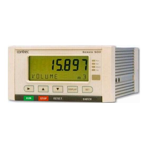
- Page 9 Backlit display with LCD backup Overview The 505 BC01 application is a dual stage batch controller for reliable measurement of preset quantities using a volumetric frequency input. Used as a single or dual stage controller it is suitable for fast batch applications.
- Page 10 Communications There are two communication ports available as follows: • RS-232 port • RS-485 port The ports are available for remote data reading, printouts and for initial application loading of the instrument. 505 BC01 - 17 June 2017...
- Page 11 All set-up parameters, totals and logged data are stored in non-volatile memory with at least 30 years retention. Frequency Relay 1 Relay 2 Input Example of dual stage Main Flow batching Volumetric Control Valve Flowmeter Control Valve Bleed Flow Figure 1 Typical Application Diagram 505 BC01 - 17 June 2017...
- Page 12 Properly shielded and grounded cables and connectors must be used in order to meet FCC emission limits. Contrec Ltd is not responsible for any radio or television interference caused by using other than recommended cables and connectors or by unauthorized changes or modifications to this equipment.
- Page 13 2400 to 19200 baud Real Time Clock (Optional) Parity Odd, even or none Battery Type 3 volts Lithium button cell (CR2032) Stop Bits 1 or 2 Battery Life 5 years (typical) Data Bits Protocols Modbus RTU, Printer* 505 BC01 - 17 June 2017...
- Page 14 24 volts DC internal, non-isolated Resolution 0.05% full scale Accuracy 0.05% full scale (20C) 0.1% (full temperature range, typical) Important: Specifications are subject to change without notice. Printer protocol is available only if RTC option is installed. 505 BC01 - 17 June 2017...
- Page 15 Rear Connectors Port 22 mm 25 mm 145 mm 138 mm Front Panel Mounting Clip Min. 189 mm 67 mm 70 mm 139 mm 147 mm Panel Cut-out Figure 2 500 Series Instrument Panel Mounting 505 BC01 - 17 June 2017...
-
Page 16: Rear Panel Connections
Single stage RELAYS RC Relay Common R2 Relay 2 Dual stage E Mains ground AC power in 95-135 V N Mains neutral MAINS or 190-260 V A Mains active RS232 port 9-pin serial port 505 BC01 - 17 June 2017... - Page 17 Reed Relay Switch Frequency Input (Fi) Signal Ground 18 Shield Coils - with 15 millivolts peak to peak AC minimum Frequency Input (Fi) Signal Ground Shield Namur Proximity Switch Vo +8V DC Frequency Input (Fi) Shield 505 BC01 - 17 June 2017...
-
Page 18: Logic Input Connection Diagram
The basic instrument has two digital outputs. The advanced option also provides a 4-20 mA output port. 4-20 mA Output Connection Figure 6 shows the connections for a 4-20 mA output. Maximum Load Resistance = 900 ohms 505 BC01 - 17 June 2017... - Page 19 Figure 7 Output Pulse Connection Diagram Control Relays The standard instrument has two relays, which are used for the dual stage batch control. The relays can drive external devices such as valves, pump circuits or external relays. 505 BC01 - 17 June 2017...
-
Page 20: Relay Connection Diagram
Communications The communication protocols are described in Communications page 45. RS-232 Port The standard RS-232 port uses terminals 4, 5 and 6 on the rear panel. 505 BC01 - 17 June 2017... - Page 21 Figure 9 shows the connection of several instruments to a computer using the RS-485 port. Twisted Pair Host Computer Load 120 ohms Comms Instrument Instrument Figure 9 RS-485 Interface Connections 505 BC01 - 17 June 2017...
- Page 22 Overall earth should be connected at the instrument end only. This connection should be as short as possible and connected to the earthing point on the rear terminal at pin 18. 505 BC01 - 17 June 2017...
- Page 23 (usually 30 seconds). • Determines what is displayed on power up or exit of Calibrate mode. Status LEDs The status LEDs illuminate to show the following conditions: 505 BC01 - 17 June 2017...
- Page 24 Hold the key to display (or edit) the batch preset or briefly press to view the accum total FLOW Volume flowrate TO RESET Hold the key to manually reset the current delivery (batch) total. 505 BC01 - 17 June 2017...
- Page 25 The display will step through the presets back to the currently entered value which can still be manually edited. While displaying the desired preset value, press the key to accept the value and exit edit mode. 505 BC01 - 17 June 2017...
- Page 26 DISPLAY information. 6. While holding the key use the key to print the data for the RESET DISPLAY displayed log if the printer option has been selected. 505 BC01 - 17 June 2017...
- Page 27 This example 2016 shows 16:15 (4:15pm) on the 27th August 2016. This function is available only if the instrument has the real time clock option. Press at any time to exit from the Model information. 505 BC01 - 17 June 2017...
- Page 28 (batch) is started. Logic Input Control This instrument allows for remote operation via the logic inputs on the rear terminals. The logic input have the following functions: • 505 BC01 - 17 June 2017...
- Page 29 42 for details on the order of priority. Batch Control Processes The batch controller can be programmed to operate in various ways including: • Manual Reset (manual start). • Automatic Reset (manual start). • Automatic Restart for continuous batches. 505 BC01 - 17 June 2017...
-
Page 30: Batch Operation With Manual Or Automatic Reset
Relay 1 Relay 2 Slow Start Time Prestop Qty Auto Restart End of Time Batch End of Batch Pump Control Figure 11 Batch Operation with Automatic Restart 505 BC01 - 17 June 2017... - Page 31 • Press to return to the main calibration menu. DISPLAY to scroll to the END 3. To exit from the Calibration View mode, press option and press The instrument returns to Normal Operation mode. 505 BC01 - 17 June 2017...
- Page 32 END, then press . Otherwise, from any menu, you can press and hold for two seconds. The instrument makes two beeps and cancels the Cal and Set indicators. Alarm 505 BC01 - 17 June 2017...
- Page 33 Units of Measurement The calibration of some parameters is based on the units that are defined for the relevant variables. These units of measurement can been viewed in the UNITS menu in calibration below. 505 BC01 - 17 June 2017...
-
Page 34: Calibration Menu Tree Sheet
CORR COUNT LINEAR NON-LIN A-OUT AUTO RESET KFACT NO-PTS selection AUTO COMP FREQ01 FREQn PT-MIN STOP FACT01 PT-MAX FACTn No-SET BATCH SET-nn BATCH DIRECT ACCES PRESET BATCH Figure 12 Calibration Menu Tree Sheet 1 505 BC01 - 17 June 2017... -
Page 35: Calibration Menu Tree Sheet
Press at any I/O assignment position to move to the next I/O assignment in the submenu (eg pressing on ALRM1 will move you to ALRM2) Figure 13 Calibration Menu Tree Sheet 2 505 BC01 - 17 June 2017... - Page 36 YES, then press the key. The instrument makes three beeps to confirm the reset command. The message -RESET- PLEASE WAIT will be displayed as the instrument exits calibration mode and completes a full re-boot sequence. 505 BC01 - 17 June 2017...
- Page 37 Enter the value in seconds. COUNT The batch count direction determines whether the batch total counts up from zero to the preset value or down from the preset to zero. Press to select UP or DOWN. 505 BC01 - 17 June 2017...
- Page 38 If disabled, the changes can only be made from within the calibration set mode (or via serial communications, see below). Select the direct access mode as required. Press to select ENABLE or DISABLE. 505 BC01 - 17 June 2017...
- Page 39 For example if the cut-off is set to 0.01 Hz, and the measured flow stops, the instrument continues to display the flow rate for 100 seconds before it can determine that the flow has actually stopped. 505 BC01 - 17 June 2017...
- Page 40 This parameter is available for viewing and editing only when the correction type is set to Linear. The K-factor of the flowmeter is the number of pulses from the flowmeter per unit of volume (or mass). The K-factor cannot be 0 (zero). 505 BC01 - 17 June 2017...
- Page 41 This parameter is available for viewing and editing only when the correction type is set to Non-linear. FACT Enter the scaling factor for this correction point in the same units of measure as the single K-factor above. The correction factor cannot be 0 (zero). 505 BC01 - 17 June 2017...
- Page 42 The output pulse factor cannot be 0 (zero). 4-20 A-OUT You can assign any of the “rate” main menu variables to the 4-20 mA output. Press to select the variable that is required as an output. 505 BC01 - 17 June 2017...
- Page 43 50 ms: 1000 -------------- - 10Hz The maximum pulse output frequency is: 2 50 ----- - The minimum pulse factor for that frequency is: 505 BC01 - 17 June 2017...
- Page 44 The stop bit setting of the instrument must match INFRA the stop bit setting of the communication device that the instrument is connected to. Press to select 1 or 2 stop bits. 505 BC01 - 17 June 2017...
- Page 45 The instrument will log a total of 100 deliveries (batches) if the real-time clock option is installed. The logs are taken at the end of each batch or upon reset if a batch has been aborted before the preset total has been reached. 505 BC01 - 17 June 2017...
- Page 46 The following printer types available in this instrument are: • PRN-01 Generic computer printer • PRN-02 Generic roll printer (prints first line first) • PRN-03 Slip printer TM295 Press to select Printer Type. 505 BC01 - 17 June 2017...
- Page 47 ACCUM The Reset Accumulated Totals function clears all of the accumulated totals and the non-accumulated totals. Press to select YES, then press the key. The instrument makes three beeps to confirm the reset command. 505 BC01 - 17 June 2017...
- Page 48 You can view the state of the logic input. If the input is an open contact or inactive it will display HI. If the input is a closed contact or active it will display LO. 505 BC01 - 17 June 2017...
- Page 49 The manufacturer or distributor can enter user-defined text for the messages. This user-defined text is displayed, instead of the default (English) messages, when the Display Tags option in the Setup menu is set to USER. 505 BC01 - 17 June 2017...
- Page 50 The system displays warning messages as described in the following table: Warning Messages Description Value Has Been Set to You have entered an invalid value for a parameter. Therefore, the Default instrument has set the default value. 505 BC01 - 17 June 2017...
- Page 51 You have tried to assign a particular protocol type to more than one Other Port serial communication port. The instrument has set the protocol to NONE. Preset Over Limit - You have exceeded the preset limit. The instrument will set the Max Set maximum allowed value. 505 BC01 - 17 June 2017...
- Page 52 Instrument Calibration 505 BC01 - 17 June 2017...
- Page 53 It is not possible to communicate directly with a printer via a parallel port. Computers use either a DB9 or a DB25 connector, and the connections to each type are shown in Figure 14. 505 BC01 - 17 June 2017...
-
Page 54: Rs-232 Cable Connections To A Computer
“daisy chained” in a multidrop configuration as shown in Figure 15. Up to 32 units can be connected to the interface at a maximum distance of 1200 metres. Twisted Pair Host Computer Load 120 ohms Comms Instrument Instrument Figure 15 RS-485 Connections 505 BC01 - 17 June 2017... - Page 55 One of four possible events can occur from the master’s query: • If the slave device receives the query without a communication error, and can handle the query normally, it returns a normal response. 505 BC01 - 17 June 2017...
- Page 56 Read data register(s) Obtain the content of one or more 2-byte data registers. Preset data register Preset one 2-byte data register. Read status register Obtain the content of 1-byte status register. Preset data register(s) Preset one or more 2-byte data registers. 505 BC01 - 17 June 2017...
- Page 57 “register 1” in this case has “address 0” and so on. Current and Logged Process Data This block of registers is available for the retrieval of current or logged process data with its matching time and date information. 505 BC01 - 17 June 2017...
- Page 58 03 - clear non-accumulated totals Reserved * DT = Data Type of 2-register (4 byte) values can be set as Floating Point or Long Integer values † I = Integer (2 bytes) (Holding Registers) 505 BC01 - 17 June 2017...
- Page 59 * I = Integer (2 bytes) (Holding Registers) Instrument Control and I/O This block of registers is available in some applications to give access to important information in the instrument. Register Name Comments Read Only or Type Read/Write Reserved Reserved 505 BC01 - 17 June 2017...
- Page 60 * I = Integer (2 bytes) (Holding Registers) † L = Long Integer (2 register = 4 bytes) ‡ DT = Data Type of 2-register (4 byte) values can be set as Floating Point or Long Integer values 505 BC01 - 17 June 2017...
- Page 61 The usage of these parameters can be dependent on other instrument settings. For full description, please refer to the Modbus Accessible Parameters on page 31. Register Name Comments Read Only or Type Read/Write Batch Preset Value 53 to 99 Reserved 505 BC01 - 17 June 2017...
- Page 62 A printout can only be initiated if a batch is not in progress. If printing is not required, do not select printer protocol. The format of this printout will be: 505 BC01 - 17 June 2017...
- Page 63 The printout will have the time and date stamp corresponding to when the log was taken. After the print has been initiated there will be the opportunity to scroll to view another log entry and print again. 505 BC01 - 17 June 2017...
- Page 64 -------------------------------------------- <separation line> Delivery No. Date & Time & Status Variable unit value Variable unit value etc. -------------------------------------------- <separation line> Delivery No. Date & Time & Status Variable unit value Variable unit value etc. 505 BC01 - 17 June 2017...
- Page 65 Some printers will also transmit an Xoff character in response to other events such as printer being off-line, print head not engaged or power being removed. The specific behaviour of the printer being used should be noted. 505 BC01 - 17 June 2017...
- Page 66 When communications timeout error has been activated the message COMMS TIMEOUT will be scrolled once, the request to print will be cleared and the instrument will return to its normal mode. 505 BC01 - 17 June 2017...
- Page 67 Note: The first character represents the CPU installed (factory use only). The remaining 6 characters only MODEL represent hardware that affects the operation. Note: Example full product part number is 505.112ESC-BC01 (this is the number used for placing orders). 505 BC01 - 17 June 2017...
- Page 68 The Application Information code is an aid for users and service personnel to determine the type of inputs that are used in a particular application. The Application Information code is displayed on the instrument as shown below. Assignment type FC01 APPL Application number 505 BC01 - 17 June 2017...
- Page 69 - indicates a density input • t - indicates a temperature input. • For example, is an instrument with FINP (frequency input) assigned to a flow input, AINP (analog input) assigned to a level input. 505 BC01 - 17 June 2017...
- Page 70 E+0, E+3, E+6 (scaling for unitless variable) Length (Level) m, mm, cm, INCH, FOOT Velocity m/s, m/M, m/h, ft/s, ft/M, ft/h Length K-Factor P/m, P/cm, P/INCH, P/FOOT Area , ft Ratio General Input Pressure, Temperature, Density, Length (Level), Factor 505 BC01 - 17 June 2017...
- Page 71 505 BC01 - 17 June 2017...
- Page 72 RS-232 12, 36, 45 RS-485 13, 36, 46 505 BC01 - 17 June 2017...
- Page 73 RS-232 port 12, 36, 45 RS-485 port 13, 36, 46 RTU protocol RUN key serial number SET key settings instrument setup menu shielding snubber specifications standards starting a batch status LEDs stop bits 505 BC01 - 17 June 2017...
Need help?
Do you have a question about the 505 BC01 and is the answer not in the manual?
Questions and answers