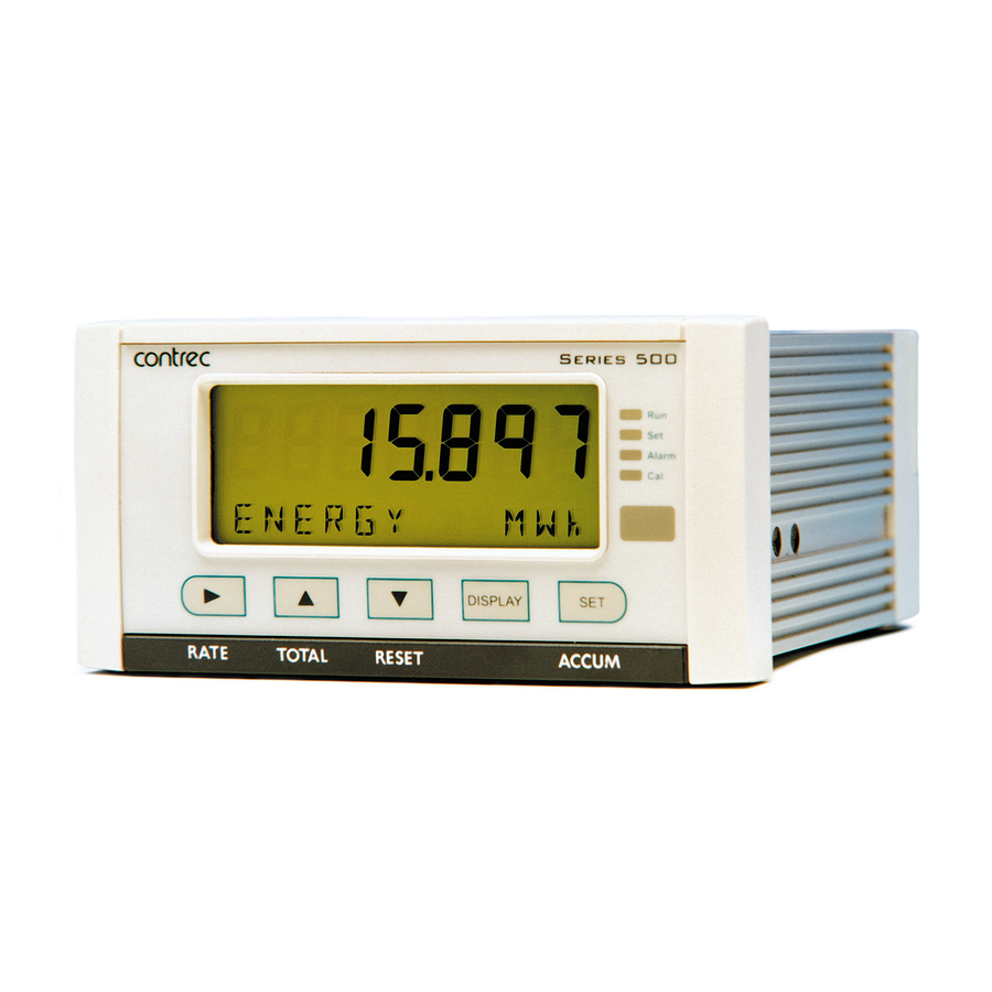
Contrec 515 Operation Manual
Flow computer.
secure dual stage batch controller
for
mass frequency flowmeters
Hide thumbs
Also See for 515:
- Operation manual (112 pages) ,
- Operation manuals (85 pages) ,
- Operation manual (88 pages)
Table of Contents
Advertisement
Quick Links
Download this manual
See also:
Operating Manual
Advertisement
Table of Contents

Related Manuals for Contrec 515


Summary of Contents for Contrec 515
- Page 1 Model 515 Flow Computer Operation Manual BS03 Application Secure Dual Stage Batch Controller Mass Frequency Flowmeters 2 April 2017...
- Page 2 Should any questions arise which cannot be answered specifically by this manual, they should be directed to Contrec Limited for further detailed information and technical assistance. Contrec Limited will not accept any liability for either direct or consequential damages resulting from the use or misapplication of the contents of this manual.
- Page 3 Disconnection Device When powered from a mains supply this unit requires the provision of a suitable mains isolation device to be accessible near to the installed instrument. 515 BS03 - 2 April 2017 515 BS03 - 2 April 2017...
- Page 4 515 BS03 - 2 April 2017...
- Page 5 RC Network for Interference Suppression Communications RS-232 Port RS-485 Port (Optional) Earthing and Shielding 4 Operation Front Panel Operation Default Variable Status LEDs Front Panel Keys Main Menu Items Setting the Batch Preset Data Logs 515 BS03 - 2 April 2017...
- Page 6 Warning Messages Prompt Messages 6 Communications Overview Hardware Interconnection Protocols Simple ASCII Protocol Requests Format Instrument Responses Corrupted or Invalid Requests Modbus RTU Protocol List of Data Registers iButton ID Tag Protocol Printer Protocol 515 BS03 - 2 April 2017...
- Page 7 Types of Printouts Printer Data Control Appendix A Glossary Glossary Appendix B Model Numbers Product Codes Custom Version Codes Application Information Code Appendix C Units of Measurement Available Units of Measurement Index 515 BS03 - 2 April 2017...
- Page 8 515 BS03 - 2 April 2017...
- Page 9 Relay Connection Diagram RS-485 Interface Connections Batch Operation with Manual or Automatic Reset Batch Operation with Automatic Restart Calibration Menu Tree Sheet 1 Calibration Menu Tree Sheet 2 RS-232 Cable Connections to a Computer RS-485 Connections 515 BS03 - 2 April 2017...
- Page 10 515 BS03 - 2 April 2017...
-
Page 11: Features
Backlit display with LCD backup Overview The 515 BS03 application is a secure dual stage batch controller for reliable measurement of preset quantities using a mass frequency input. The instrument can be set to accept a valid ID-Tag, via an ‘iButton’ reader on the serial port and/or prompt for connection of a permissive before a batch can be commenced. -
Page 12: Calculations
Variable Variables Units Type Mass Total Mass Flowrate kg/min Rate Batch ID Tag - - - - - - Refer to Available Units of Measurement on page 82 for the list of available units. 515 BS03 - 2 April 2017... -
Page 13: Communications
Instrument parameters including units of measurement can be programmed in the field, according to the user access levels assigned to parameters by the distributor. All set-up parameters, totals and logged data are stored in non-volatile memory with at least 30 years retention. 515 BS03 - 2 April 2017... -
Page 14: Specialised Uses
In this case the display would show the back draining product being deducted from the current net batch total. In On-Off mode the operator determines the start and end of the delivery by using the front or remote keys. 515 BS03 - 2 April 2017... -
Page 15: Approvals
Residential, Commercial & Light Industry Environment & Industrial Environment. • EN61010:2010 Safety requirements for electrical equipment for measurement, control, and laboratory use. In order to comply with these standards, the wiring instructions in Chapter 3 - Installation must be followed. 515 BS03 - 2 April 2017... - Page 16 Introduction 515 BS03 - 2 April 2017...
-
Page 17: Specifications Specification Table
2400 to 19200 baud Battery Type 3 volts Lithium button cell (CR2032) Parity Odd, even or none Battery Life 5 years (typical) Stop Bits 1 or 2 Data Bits Protocols ASCII, Modbus RTU, Printer*, ID-Tag 515 BS03 - 2 April 2017... - Page 18 9 to 30 volts DC external Resolution 0.05% full scale Accuracy 0.05% full scale (20C) 0.1% (full temperature range, typical) Important: Specifications are subject to change without notice. Printer protocol is available only if RTC option is installed. 515 BS03 - 2 April 2017...
-
Page 19: Installation Panel Mounting
Rear Connectors Port 22 mm 25 mm 145 mm 138 mm Front Panel Mounting Clip Min. 189 mm 67 mm 70 mm 139 mm 147 mm Panel Cut-out Figure 2 500 Series Instrument Panel Mounting 515 BS03 - 2 April 2017... -
Page 20: Electrical Connection
17 Vi + DC power input DC power in 12-28V RS232 port 9-pin serial port 18 SH E Shield terminal E Mains ground AC power in 100- N Mains neutral MAINS 240VAC A Mains active 515 BS03 - 2 April 2017... -
Page 21: Inputs
Reed Relay Switch Frequency Input (FINPn) Signal Ground 18 Shield Coils - with 15 millivolts peak to peak AC minimum Frequency Input (FINPn) Signal Ground Shield Namur Proximity Switch Vo +8V DC Frequency Input (FINPn) Shield 515 BS03 - 2 April 2017... -
Page 22: Logic Input Connection
Figure 5 shows the connections for a 4-20 mA output. Output channel 1 uses terminals 27 (+) and 28 (-), output channel 2 uses terminals 29 (+) and 30 (-). Maximum Load Resistance = (Supply-9) / 0.02 ohms 515 BS03 - 2 April 2017... -
Page 23: Digital Output Connection
The advanced option has two extra relays that can be freely assigned as alarm relays. The operation of alarm relay(s) can be set to various modes as described in Alarms on page 43. 515 BS03 - 2 April 2017... -
Page 24: Rc Network For Interference Suppression
However, if the user is unsure of the type of snubber to use, values of 0.25 F and 100 will usually suffice. Note that only mains-approved RC suppression networks should be used. 515 BS03 - 2 April 2017... -
Page 25: Communications
Up to 32 units can be connected to a common RS-485 bus. Each unit has a unique address that the host computer uses to identify each instrument. Figure 8 shows the connection of several instruments to a computer using the RS-485 port. 515 BS03 - 2 April 2017... -
Page 26: Earthing And Shielding
Overall earth should be connected at the instrument end only. This connection should be as short as possible and connected to the earthing point on the rear terminal at pin 18. 515 BS03 - 2 April 2017... -
Page 27: Operation Front Panel Operation
There are several categories of information that the instrument can display: • Totals • Rates • Batch preset values • Instrument settings For each total, there is an associated rate as follows: Total Rate Mass Mass Flowrate 515 BS03 - 2 April 2017... -
Page 28: Default Variable
Continue to BATCH BATCH hold for two seconds to enter edit mode for the preset if access is authorised. Pressing the key briefly displays the accumulated total. BATCH 515 BS03 - 2 April 2017... -
Page 29: Main Menu Items
Limit on Batch Size To prevent accidental entry of large batch quantities, a maximum batch limit can be programmed during calibration. The operator is then prevented from entering a batch quantity which exceeds this value. 515 BS03 - 2 April 2017... -
Page 30: Data Logs
4. Press the key to show the information stored in the selected log DISPLAY record. Each log record consists of: • time and date stamp, • error code 515 BS03 - 2 April 2017... -
Page 31: Model Information
80 for more information. 2_9_031 The version of software loaded into the instrument. 500PM VERS 026357 The Customer version code for this installation. Refer Custom Version Codes on page 80 for more CUSTOM VERS information. 515 BS03 - 2 April 2017... -
Page 32: Batch Operation Modes
An auto-restart feature for automated repeat batches is also available in preset mode. On-Off Mode If the batch mode is ON-OFF the shut-off point is determined by the operator. 515 BS03 - 2 April 2017... -
Page 33: Unload Mode
A prompt to ‘Connect Permissive’ is scrolled on the display if the permissive circuit is not closed. The Permissive Input feature can be enabled or disabled within the Parameters section of calibration. 515 BS03 - 2 April 2017... -
Page 34: Starting A Batch
STOP led turns off. When the process is in pause mode, the RUN led will flash to prompt the operator to restart or abort the batch. 515 BS03 - 2 April 2017... -
Page 35: Resetting A Batch
Previous (logged) delivery transactions can be reprinted from within the LOGGED DATA menu by scrolling to the desired DEL number, then while holding the key, press ) key to initiate a DISPLAY RESET PRINT reprint. 515 BS03 - 2 April 2017... -
Page 36: Logic Input Control
A ‘Quadrature Input’ error can be cleared with a single press the RESET without resetting the totals. A quadrature error will not deactivate the control relays but the error message will be scrolled and the alarm led flashed. 515 BS03 - 2 April 2017... -
Page 37: Batch Control Processes
Reset Reached Count Down Batch Total Count Up Relay 1 Relay 2 Slow Start Time Prestop Qty End of Batch End of Batch Pump Control Figure 9 Batch Operation with Manual or Automatic Reset 515 BS03 - 2 April 2017... - Page 38 Reached Count Down Batch Total Count Up Relay 1 Relay 2 Slow Start Time Prestop Qty Auto Restart End of Time Batch End of Batch Pump Control Figure 10 Batch Operation with Automatic Restart 515 BS03 - 2 April 2017...
-
Page 39: Instrument Calibration Introduction
• Press to return to the main calibration menu. DISPLAY to scroll to the END 3. To exit from the Calibration View mode, press option and press The instrument returns to Normal Operation mode. 515 BS03 - 2 April 2017... -
Page 40: Calibration Set Mode
END, then press . Otherwise, from any menu, you can press and hold for two seconds. The instrument makes two beeps and cancels the Cal and Set indicators. Alarm 515 BS03 - 2 April 2017... -
Page 41: Changing The Instrument Settings
Units of Measurement The calibration of some parameters is based on the units that are defined for the relevant variables. These units of measurement can been viewed in the UNITS menu in calibration below. 515 BS03 - 2 April 2017... -
Page 42: Calibration Menu Tree
STOP OP-ERR FREQ01 FREQn OP-CTRL DELAY No-SET BATCH FACT01 OP-END FACTn selection SET-nn BATCH 4-20 mA PULSE DIRECT ACCES PT-MIN WIDTH WIDTH PRESET BATCH PT-MAX PULSE PULSE Figure 11 Calibration Menu Tree Sheet 1 515 BS03 - 2 April 2017... - Page 43 I/O assignment position to move to the next I/O assignment in the submenu (eg pressing on ALRM1 will move you to ALRM2 if it exists) Figure 12 Calibration Menu Tree Sheet 2 515 BS03 - 2 April 2017...
-
Page 44: Instrument Settings
YES, then press the key. The instrument makes three beeps to confirm the reset command. The message -RESET- PLEASE WAIT will be displayed as the instrument exits calibration mode and completes a full re-boot sequence. 515 BS03 - 2 April 2017... -
Page 45: Parameters
The batch automatic restart time determines the time that will elapse between the end of one batch and the start of the next. A value of zero disables the auto restart feature. Enter the value in seconds. 515 BS03 - 2 April 2017... - Page 46 To provide faster access to commonly used preset values a number of batch presets can be preprogrammed into the instrument. This parameter allows the number of batch presets to be entered. Press to select a number between 1 and 10. 515 BS03 - 2 April 2017...
-
Page 47: Inputs
Hertz in a range of 10 to 100. INPUT For this application, the Frequency Input Channel 1 is assigned to mass M-FLOW FINP1 flowrate. SIGNAL FINP1 Frequency input 1 signal type. Press to select COIL, NPS or PULSE. 515 BS03 - 2 April 2017... - Page 48 For example if the cut-off is set to 0.01 Hz, and the measured flow stops, the instrument continues to display the flow rate for 100 seconds before it can determine that the flow has actually stopped. 515 BS03 - 2 April 2017...
- Page 49 This parameter is available for viewing and editing only when the correction type is set to Linear. The K-factor of the flowmeter is the number of pulses from the flowmeter per unit of volume (or mass). The K-factor cannot be 0 (zero). 515 BS03 - 2 April 2017...
- Page 50 This parameter is available for viewing and editing only when the correction type is set to Non-linear. FACT Enter the scaling factor for this correction point in the same units of measure as the single K-factor above. The correction factor cannot be 0 (zero). 515 BS03 - 2 April 2017...
-
Page 51: Outputs
1.000 generates one pulse for . Similarly, a pulse factor of 3.000 generates one pulse for 3 m For more information, see Output Pulse Factor on page 42. The output pulse factor cannot be 0 (zero). 515 BS03 - 2 April 2017... - Page 52 50 ms: 1000 -------------- - 10Hz The maximum pulse output frequency is: 2 50 ----- - The minimum pulse factor for that frequency is: 515 BS03 - 2 April 2017...
-
Page 53: Alarms
Each alarm is completely independent, e.g. a High alarm does NOT need to have a higher setpoint than the a Low alarm. 515 BS03 - 2 April 2017... -
Page 54: Communications
Infra-red Port - Discontinued - Although program settings may be visible in calibration, the required hardware is no longer available. The PROTOC INFRA Infra-red protocol assignment ( ) should be set to NONE INFRA and the remaining settings can be ignored. 515 BS03 - 2 April 2017... - Page 55 1 or 2 stop bits. DATA The Modbus RTU data format for the 2-register (4-byte) values can be set as either floating point or long integer values. to select FLOAT or INTEGER. 515 BS03 - 2 April 2017...
-
Page 56: Time Settings And Data Logging
The instrument will log a total of 1000 deliveries (batches) if the real-time clock option is installed. The logs are taken at the end of each batch or upon reset if a batch has been aborted before the preset total has been reached. 515 BS03 - 2 April 2017... - Page 57 The Printer Protocol Report Type determines the nature of the printout from the REPORT PRINT - HOLD.SET prompt in the main menu. The following report types available in this instrument are: • REP-10 Preset number of latest logs Press to select Report Type. 515 BS03 - 2 April 2017...
-
Page 58: General Setup Parameters
Press to select the default variable display. SUPPLY VOLT The instrument provides a power-limited supply for external transducers. Press to set the transducer supply voltage between 8 and 24 volts DC as required. 515 BS03 - 2 April 2017... - Page 59 Note: The user-defined tags can be entered into the instrument only by the manufacturer or the distributor. Press to select the Display Tags option as follows: • DEFAULT - the instrument displays the default (English) tags • USER - the instrument displays the user-defined tags. 515 BS03 - 2 April 2017...
-
Page 60: Test Menu
The Test menu enables you to view the inputs and outputs to and from the instrument. In Calibration Set mode, (by entering the system password) you can control the outputs and the alarms as described in the table below. 515 BS03 - 2 April 2017... -
Page 61: System Messages
If the actual supply voltage is lower than the preset value (refer to General Setup Parameters on page 48) it may indicate that the output is overloaded. System Messages The instrument displays messages for defined events and fault conditions. 515 BS03 - 2 April 2017... -
Page 62: Error Messages
Quad The quadrature input frequency is over the limit (no pulse security Frequency checking is performed). The exception is only raised if the Over Limit quadrature input has been enabled. 515 BS03 - 2 April 2017... -
Page 63: Warning Messages
The system displays prompt messages as described in the following table: Prompt Messages Description Connect Permissive Connect permissive to proceed with batching. Validate ID Tag Validate ID Tag to proceed with batching. Press Run Key Press Run key to start batching. 515 BS03 - 2 April 2017... - Page 64 Instrument Calibration 515 BS03 - 2 April 2017...
-
Page 65: Communications Overview
It is not possible to communicate directly with a printer via a parallel port. Computers use either a DB9 or a DB25 connector, and the connections to each type are shown in Figure 13. 515 BS03 - 2 April 2017... - Page 66 14. Up to 32 units can be connected to the interface at a maximum distance of 1200 metres. Twisted Pair Host Computer Load 120 ohms Comms 19 20 21 19 20 21 Instrument Instrument Figure 14 RS-485 Connections 515 BS03 - 2 April 2017...
-
Page 67: Protocols
• iButton ID-TAG - This protocol allows an external “ibutton LINK45” module to be connected to 515 instrument to read identification tags to ensure only authorised deliveries are made. • Printer - In the Printer protocol there is a selection of printer types. -
Page 68: Requests Format
Likewise, there is only one set of current process variables with “non-accumulated totals”, therefore it also ignores any log number included in that request. 515 BS03 - 2 April 2017... -
Page 69: Instrument Responses
8 9 1 2 3 . 4 5 6 V O L U M E 10 11 12 13 14 15 16 17 18 19 20 22 23 24 25 26 27 Value (aligned right) Unit (aligned left) Item (aligned left) 515 BS03 - 2 April 2017... - Page 70 K J / K G S P - E N T The following message to an instrument, requests the current values for the default rate and total: : A 0 0 1 : R V D ? 515 BS03 - 2 April 2017...
- Page 71 Clear the logs except for the “last edited” log Clear Data Request Example The following message asks the instrument with address 001 to clear the logged data that the instrument stores: : A 0 0 1 : R C L ? 515 BS03 - 2 April 2017...
-
Page 72: Corrupted Or Invalid Requests
For example, if the instrument received the following request variables message :A001:RVT? it will return only the header because there is no T option for the ‘Variables Request’ message. 515 BS03 - 2 April 2017... -
Page 73: Modbus Rtu Protocol
The address of the instrument is programmable in the range from 1 to 247. Some addresses are reserved according to PI-MBUS-300 and have a special meaning: • 0 = Broadcast, no response required from slave devices • 248 to 255 Reserved 515 BS03 - 2 April 2017... -
Page 74: List Of Data Registers
The registers are grouped in blocks that relate to a particular function of the instrument. Note: Conventional numbering of registers often starts from 1, therefore be aware that “register 1” in this case has “address 0” and so on. 515 BS03 - 2 April 2017... - Page 75 * DT = Data Type of 2-register (4 byte) values can be set as Floating Point or Long Integer values † L = Long Integer (2 registers = 4 bytes) ‡ I = Integer (2 bytes) (Holding Registers) 515 BS03 - 2 April 2017...
- Page 76 33 = alarm 4 active * I = Integer (2 bytes) (Holding Registers) Instrument Control and I/O This block of registers is available in some applications to give access to important information in the instrument. 515 BS03 - 2 April 2017...
- Page 77 0 = Idle/Local Control from logic inputs 1 = Stop Suspend current batch 2 = Run Resume/start batch 3 = Reset Clear current batch totals ‡ 51 to 99 Instrument See next table for details. Parameters 515 BS03 - 2 April 2017...
- Page 78 * I = Integer (2 bytes) (Holding Registers) † L = Long Integer (2 register = 4 bytes) ‡ DT = Data Type of 2-register (4 byte) values can be set as Floating Point or Long Integer values 515 BS03 - 2 April 2017...
- Page 79 100 ID Tag numbers can be stored in the instrument). Register Name Comments Read Only or Type Read/Write ID Tag 001 ID Tag 002 ..ID Tag 099 ID Tag 100 515 BS03 - 2 April 2017...
-
Page 80: Ibutton Id Tag Protocol
LINK45 module, mini null modem gender changer, stainless steel panel mounting read head and cable. If the RS232 port on the 515 is used for other communications, it is possible to connect the LINK45 module to the RS485 port via a serial RS232 to RS485 convertor. -
Page 81: Printer Protocol
A printout can only be initiated if a batch is not in progress. If printing is not required, do not select printer protocol. The format of this printout will be: 515 BS03 - 2 April 2017... - Page 82 The printout will have the time and date stamp corresponding to when the log was taken. After the print has been initiated there will be the opportunity to scroll to view another log entry and print again. 515 BS03 - 2 April 2017...
- Page 83 -------------------------------------------- <separation line> Delivery No. Date & Time & Status Variable unit value Variable unit value etc. -------------------------------------------- <separation line> Delivery No. Date & Time & Status Variable unit value Variable unit value etc. 515 BS03 - 2 April 2017...
-
Page 84: Printer Data Control
Some printers will also transmit an Xoff character in response to other events such as printer being off-line, print head not engaged or power being removed. The specific behaviour of the printer being used should be noted. 515 BS03 - 2 April 2017... - Page 85 When a communications timeout error has been activated the message COMMS TIMEOUT will be scrolled once, the request to print will be cleared and the instrument will return to its normal mode. 515 BS03 - 2 April 2017...
- Page 86 Communications 515 BS03 - 2 April 2017...
-
Page 87: Appendix A Glossary Glossary
A normalised input ranges from 0 to 1.000. For 4-20 mA input, the signal is Input set to 0 at 4 mA and the signal is set to 1.000 at 20 mA. Passive Output Requires an external power supply. Signal 515 BS03 - 2 April 2017... - Page 88 515 BS03 - 2 April 2017...
-
Page 89: Appendix B Model Numbers Product Codes
For example: Model No. 515.111UFC Displayed on the 500 Series as:(only h/w that MODEL affects the operation is represented) Note: Example full product part number is 515.111UFC-BS03 (This is the number used for placing orders). 515 BS03 - 2 April 2017... -
Page 90: Custom Version Codes
Factory Default Application Contrec Systems Pty. Ltd. Melbourne Australia Contrec Manufacturing Limited. West Yorkshire UK Origin Code Contrec Europe Ltd. West Yorkshire UK Identifies Contrec - USA, LLC. Pelham AL 35124 USA Distributor Flowquip Ltd. Halifax UK etc. English (Default) German... - Page 91 For example, is an instrument with FINP1 (frequency input 1) assigned to a flow input, AINP1 assigned to a temperature input and AINP2 assigned as a pressure input. The other inputs are not used. 515 BS03 - 2 April 2017...
-
Page 92: Appendix C Units Of Measurement Available Units Of Measurement
E+0, E+3, E+6 (scaling for unitless variable) Length (Level) m, mm, cm, INCH, FOOT Velocity m/s, m/M, m/h, ft/s, ft/M, ft/h Length K-Factor P/m, P/cm, P/INCH, P/FOOT Area , ft Ratio General Input Pressure, Temperature, Density, Length (Level), Factor 515 BS03 - 2 April 2017... -
Page 93: Index
515 BS03 - 2 April 2017... - Page 94 Modbus accessible parameters installation Modbus data format instrument Modbus RTU protocol address mode request format display timeout responses set calibration settings view calibration interconnections, communication model numbers interference suppression modes, batch control isolated outputs mounting 515 BS03 - 2 April 2017...
- Page 95 SET key preset batch value setpoint, alarm preset mode settings printer instrument data control setup menu error messages shielding protocol snubber report types specifications printer types standards printing a docket starting a batch 515 BS03 - 2 April 2017...
- Page 96 TOTAL key unit tag units menu validate ID tag variable, default version, customer view data logs warnings 515 BS03 - 2 April 2017...
Need help?
Do you have a question about the 515 and is the answer not in the manual?
Questions and answers