Contrec 515 Operation Manual
Flow computer, ratio/blending process controller for volumetric analog flowmeters, application cr02
Hide thumbs
Also See for 515:
- Operation manual (112 pages) ,
- Operation manuals (85 pages) ,
- Operation manual (90 pages)

Related Manuals for Contrec 515


Summary of Contents for Contrec 515
- Page 1 Model 515 Flow Computer Operation Manual CR02 Application Ratio/Blending Process Controller Volumetric Analog Flowmeters 31 August 2021...
- Page 2 Should any questions arise which cannot be answered specifically by this manual, they should be directed to Contrec Limited for further detailed information and technical assistance. Contrec Limited will not accept any liability for either direct or consequential damages resulting from the use or misapplication of the contents of this manual.
- Page 3 Operating & Storage Temperature Operating: If a heater is being used, DO NOT isolate the instrument in temperatures below -20°C. Storage: DO NOT store the equipment below -20°C. 515 CR02 - 31 August 2021 515 CR02 - 31 August 2021...
- Page 4 Instrument Disposal Contrec instrumentation should not be thrown into the general waste system. If within EU member states, this instrument should be disposed of according to the guidelines set by the WEEE (Waste Electrical and Electronic Equipment) directive 2012/19/EU.
-
Page 5: Table Of Contents
Logic Input Connection Outputs 4-20 mA Output Connection Pulse Output Connection Control Relays (Alarms) RC Network for Interference Suppression Communications COM-1 RS-232 Port COM-2 RS-485 Port Option COM-2 Ethernet Port Option Mains Connection Earthing and Shielding 515 CR02- 31 August 2021... - Page 6 Upload and Clone of Application Software Calibration Menu Tree Instrument Settings Units of Measurement Parameters Inputs Outputs Alarms Communications Time Settings and Data Logging General Setup Parameters Test Menu System Messages Error Messages Warning Messages 515 CR02- 31 August 2021...
- Page 7 Printer Data Control Appendix A Glossary Glossary Appendix B Model Numbers Product Codes Custom Version Codes Application Information Code Appendix C Ethernet Port & Setup Ethernet Port Connecting 515 Ethernet to Networks/Routers Connecting DataMod via Ethernet Index 515 CR02- 31 August 2021...
- Page 8 515 CR02- 31 August 2021...
- Page 9 Output Pulse Connection Diagram Relay Connection Diagram RS-485 Interface Connections Logged Data Display Methods Calibration Menu Tree Sheet 1 Calibration Menu Tree Sheet 2 RS-232 Cable Connections to a Computer RS-485 Connections DataMod - Modbus Connection Settings 515 CR02- 31 August 2021...
- Page 10 515 CR02- 31 August 2021...
-
Page 11: Introduction
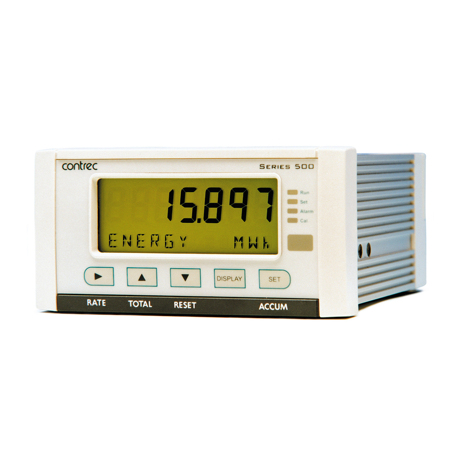
Backlit display with LCD backup Overview The 515 CR02 application is a single loop process controller measuring the volume flow in a main and process lines using analog flow inputs. It can operate in local (manual) or in loop, ratio or blend (auto) flow control modes and it has a tuning menu to easily determine the Proportional Band and Integral Time values used in the PI control algorithm. -
Page 12: Calculations
• NON-LINEAR: when the instrument applies correction from the points in the correction table Displayed Information The front panel display shows the current values of the input variables and the results of the calculations. 515 CR02 - 31 August 2021... -
Page 13: Main Menu Variables
The relay output 1 provides a pump demand contact and the other relays can be used as fully programmable alarms for any rate type variable. Two relays are standard with an additional two available in the advanced option. 515 CR02 - 31 August 2021... -
Page 14: Software Configuration
The software is a Windows based program that is freely available from the download section of the Contrec website. The program can be used to create a custom version of an existing application to be saved for backup purposes and/or to generate a PDF of configuration report for record keeping. - Page 15 Properly shielded and grounded cables and connectors must be used in order to meet FCC emission limits. Contrec Ltd is not responsible for any radio or television interference caused by using other than recommended cables and connectors or by unauthorized changes or modifications to this equipment.
- Page 16 Introduction 515 CR02 - 31 August 2021...
-
Page 17: Specifications Specification Table
BR2032 and CR2032 manufactured by Current 70 mA @ 24 V, 120 mA @ 12 V maximum Panasonic or Sony Protection Power limited output Battery Life 5 years (typical) 515 CR02 - 31 August 2021 515 CR02 - 31 August 2021... - Page 18 Programmable: 10 , 20, 50, 100, 200 or 500ms 4-20 mA Output Supply 9 to 30 volts DC external Resolution 0.05% full scale Accuracy 0.05% full scale (20C) 0.1% (full temperature range, typical) Important: Specifications are subject to change without notice. 515 CR02 - 31 August 2021...
-
Page 19: Installation & Maintenance
Rear Connectors Port 22 mm 25 mm 145 mm 138 mm Front Panel Mounting Clip Min. 189 mm 67 mm 70 mm 139 mm 147 mm Panel Cut-out Figure 2 500 Series Instrument Panel Mounting 515 CR02 - 31 August 2021... -
Page 20: Electrical Connection
Note: On these option cards the 6 way relay terminal block is ORANGE. Figure 4 shows the new option card with the RS-485 port (terminals 19-21). Figure 4 Rear Panel Connections - New RS-485 Version 515 CR02 - 31 August 2021... -
Page 21: Terminal Designations
R4 Relay 4 AC power in 100- N Mains neutral Term 36 only available on MAINS RC Relay common 3-4 240VAC new style option card A Mains active RS232 COM-1 port 9-pin serial port 515 CR02 - 31 August 2021... -
Page 22: Terminal Wiring Insulation
Electrical Code of Practice as dictated by the Authority Having Jurisdiction (AHJ). The terminal designations (L/N/E) are clearly indicated just above the mains input connector on the rear panel of the instrument. 515 CR02 - 31 August 2021... -
Page 23: Inputs
4-20 mA Inputs For externally powered current loops, connect each transmitter to a pair of input terminals as shown in Figure 8. Terminal Designations on page 11 for specific terminal numbers for this application. 515 CR02 - 31 August 2021... -
Page 24: Logic Input Connection
300ms is required to guarantee reading of an input. It is possible to read the status of all the logic inputs via a Modbus register even if they are not used for a control purpose in the application. 515 CR02 - 31 August 2021... -
Page 25: Outputs
27 (+) and 28 (-), output channel 2 uses terminals 29 (+) and 30 (-). Maximum Load Resistance = (Supply - 9) / 0.02 ohms 4-20 mA DC supply Output 9...24V (OUTn) Load Shield Figure 11 Output 4-20 mA Connection Diagram 515 CR02 - 31 August 2021... -
Page 26: Pulse Output Connection
27 (+) and 28 (-). Output channel 2 uses terminals 29 (+) and 30 (-). Vo +8...24V DC External Load Resistor 10K Logic Input Open Pulse Output Collector (OUTn) Output DC Ground Shield Figure 12 Output Pulse Connection Diagram 515 CR02 - 31 August 2021... -
Page 27: Control Relays (Alarms)
Note: Solid state relays (SSR) use AC voltage only. Relay 1 RC Relay 1-2 Common Supply Pump Relay 2 Control Alarm Relay 3 Alarm Relay 4 Alarm Supply Relay 3-4 Common Figure 13 Relay Connection Diagram 515 CR02 - 31 August 2021... -
Page 28: Rc Network For Interference Suppression
The basic principle of the operation is that the capacitor prevents a series of sparks arcing across the contact as the contact breaks. The series resistor limits the current through the contact when the contact first makes. 515 CR02 - 31 August 2021... -
Page 29: Communications
Figure 14 shows the connection of several instruments to a computer using the RS-485 port. Twisted Pair Host Computer Load 120 ohms Comms 19 20 21 19 20 21 Instrument Instrument Figure 14 RS-485 Interface Connections 515 CR02 - 31 August 2021... -
Page 30: Com-2 Ethernet Port Option
If mounted in an ExD enclosure, before proceeding, refer to the ExD manual for further information. This work may need to be scheduled and carried out in accordance with the local electrical Code of Practice. 515 CR02 - 31 August 2021... -
Page 31: Battery Replacement
2. Conformal coated “C” version - Type BR2032, manufacturer Panasonic ONLY. 3. Non Conformally coated versions :- BR2032, CR2032, Sony or Panasonic ONLY. *Issue 7 option card can be identified with 6 way (31-36) ORANGE relay connector. 515 CR02 - 31 August 2021... - Page 32 Installation & Maintenance 515 CR02 - 31 August 2021...
-
Page 33: Operation
Slow Flashing LED: The ‘Force Local’ (manual) mode is active Alarm The instrument is in Calibrate Set mode. Alarm The instrument has an error, as indicated on the display panel. The instrument is in Calibrate View mode. 515 CR02 - 31 August 2021... -
Page 34: Front Panel Keys
See below for further details of peak flowrates. Remote Reset The Remote Reset on logic input 3 (LINP3) has the same function as the front key, as described above. RESET 515 CR02 - 31 August 2021... -
Page 35: Main Menu Items
Model Menu information as described in Model Information on page 29 CAL MENU Only shown in Detail Hold the key to enter Calibration View Menu mode as described in Calibration View Mode page 38 515 CR02 - 31 August 2021... -
Page 36: Detail And Basic Menu
Operation Detail and Basic Menu The 515 instrument has the option to switch the main menu from the full Detail menu to a Basic menu. The Detail menu includes all of the main menu variables and the HOLD SET sub menu items as listed above. In the Basic menu only the application or operator essential main menu variables are shown. -
Page 37: Data Logs
The following example shows the hourly log number 006 at 15:00 (3:00 pm) on 16 January 2018. The day and month alternate with the year in the bottom right hand corner. 15-00 15-00 LH-006 2019 LH-006 16/01 515 CR02 - 31 August 2021... - Page 38 … … DISPLAY Hold … show the values for Variable 2 a log entry Variable 1 DISPLAY and press Hold Error code display the main menu variables Figure 15 Logged Data Display Methods 515 CR02 - 31 August 2021...
-
Page 39: Model Information
Reset to start the printing of the configuration report. The report will be in a similar format to the report generated by the 500-Series Program Manager. Press at any time to exit from the Model information. 515 CR02 - 31 August 2021... -
Page 40: Process Control Modes
Output The control of the process line is Main Flow independent of the main flow. Proportional Flowmeters Control Valve Process Flow The main flow input can be used and measured but is not neccessary. 515 CR02 - 31 August 2021... - Page 41 Input 4 Output The desired process flow is determined as a Main Flow ratio of the main flow (0 to 400% range) i.e. Proportional Flowmeters Control Valve Process Flow -------------- flow Ratio% flow 515 CR02 - 31 August 2021...
- Page 42 Main Flow The desired process flow is determined as a ratio of the main (net) flow (0 to 80% Main range). i.e. Flowmeter Process Flow Process Proportional -------------- flow Ratio% Flowmeter Control Valve flow 515 CR02 - 31 August 2021...
-
Page 43: Logic Input Controls
Unless the menu is quit the program will step back to start of the tuning menu so that new values of P-BAND and I-TIME can be entered and the effect of a step change in the setpoint be monitored. 515 CR02 - 31 August 2021... -
Page 44: Tuning The Ratio Trim Control
(the process flowrate). Trim control only applies to the Ratio and Blend control modes. The Trim Time (T-TIME) is entered as a part of the parameters menu in calibration when either of these modes are selected. 515 CR02 - 31 August 2021... - Page 45 Increase or decrease the T-TIME to achieve the desired response. The Deadband and the Output Ramp Time can now be programmed as required. The stability of the loop should be again checked at a few different working flowrates and ratios. 515 CR02 - 31 August 2021...
- Page 46 Operation 515 CR02 - 31 August 2021...
-
Page 47: Instrument Calibration
“programmable” parameters, but the correct password must be entered to change the password-protected parameters. Likewise, the CAL switch (Logic Input 4) must be used to enter Calibration Set mode to change the CAL switch protected parameters. 515 CR02 - 31 August 2021... -
Page 48: Calibration View Mode
To select the next digit, press 6. Press or use the CAL switch on Logic Input 4 (if “Cal switch protected” items exist) to accept the password and proceed. 7. Proceed and observe the access confirmations. 515 CR02 - 31 August 2021... - Page 49 “Cal switch protected” items exist, the CAL switch can be closed for two seconds. The instrument makes two beeps and cancels the Cal and Set indicators. Alarm 515 CR02 - 31 August 2021...
-
Page 50: Changing The Instrument Settings
The calibration of some parameters is based on the units that are defined for the relevant variables. These units of measurement can been viewed in the UNITS menu in the Instrument Settings section below. 515 CR02 - 31 August 2021... -
Page 51: Program Backup & Reports
To assist in keeping an audit trail of the program settings and changes made via the front panel, the 515 instrument provides the ability to print the configuration to a local printer if one has been connected and assigned to one of the 515 communication ports. -
Page 52: Calibration Menu Tree
D-BAND selection E-TIME R-TIME TYPE ACTIVE CTRL E-TIME POINT DIRECT ACCES ACTIVE CTRL HYST P-FLOW DIRECT ACCES DELAY P-FLOW value RATIO DEVIAT RATIO value value DEVIAT value Figure 16 Calibration Menu Tree Sheet 1 515 CR02 - 31 August 2021... - Page 53 I/O assignment position to move to the next I/O assignment in the submenu (eg pressing on ALRM1 will move you to ALRM2 if it exists) Figure 17 Calibration Menu Tree Sheet 2 515 CR02 - 31 August 2021...
-
Page 54: Instrument Settings
YES, then press the key. The instrument makes three beeps to confirm the reset command. The message -RESET- PLEASE WAIT will be displayed as the instrument exits calibration mode and completes a full re-boot sequence. 515 CR02 - 31 August 2021... -
Page 55: Parameters
Enter the value as a percentage of the Flow Range parameter. While the main menu Deviation (error) is within the deadband, the process control signal will remain steady (i.e. the error is treated as zero in the algorithm). 515 CR02 - 31 August 2021... - Page 56 399.999%. For blend mode the value must be within the range 0 to 80%. If RATIO or BLEND control mode the live RATIO and DEVIATION values are now shown to give immediate feedback without leaving calibration set mode. 515 CR02 - 31 August 2021...
-
Page 57: Inputs
As a guide to the degree of filtering to use, the following table shows the response time (in seconds) to reach 90% and 99% of a step change in input. The value A is the filter constant that the user can set. 515 CR02 - 31 August 2021... - Page 58 This parameter is available for viewing and editing only when the AINP4 correction type is set to Non-linear. Enter the number of non-linearity correction points. Press to select a number between 1 and 20 for the number of correction points. 515 CR02 - 31 August 2021...
-
Page 59: Outputs
ALARMS COMMS TM/LOG SETUP TEST END Note: In the factory default version of this application output channel 1 ( ) is dedicated OUT1 as the 4-20mA Process Control signal. Output channel 2 can be freely configured. 515 CR02 - 31 August 2021... - Page 60 1.000 generates one pulse for . Similarly, a pulse factor of 3.000 generates one pulse for 3 m For more information, see Output Pulse Factor on page 51. The output pulse factor cannot be 0 (zero). 515 CR02 - 31 August 2021...
- Page 61 50 ms: 1000 -------------- - 10Hz The maximum pulse output frequency is: 2 50 ----- - The minimum pulse factor for that frequency is: 515 CR02 - 31 August 2021...
-
Page 62: Alarms
BD-NC - Band Alarm, contacts are Normally Closed • AL-NO - Equipment Alarm, contacts are Normally Open • AL-NC - Equipment Alarm, contacts are Normally Closed Press to select the type of alarm required. 515 CR02 - 31 August 2021... -
Page 63: Communications
Ethernet connection requires COM-2 setting to be: RTU (Modbus), 19200 Baud rate, even parity and 1 stop bit. • COM-3 Port - A special communications port that is only applicable to some applications. 515 CR02 - 31 August 2021... - Page 64 1 or 2 stop bits. DATA The Modbus RTU data format for the 2-register (4-byte) values can be set as either floating point or long integer values. to select FLOAT or INTEGER. 515 CR02 - 31 August 2021...
-
Page 65: Time Settings And Data Logging
In this case, you should set the current time and date so that the instrument continues to log data at the correct times. 515 CR02 - 31 August 2021... - Page 66 YEAR LOGS Set the number of Yearly Logs to appear on the printed log report. The yearly log entry occurs at 00 hours and 00 minutes on the first day of the year. 515 CR02 - 31 August 2021...
- Page 67 Slip printer TM295 • PRN-04 Label (roll) printer - Citizen CMP30L Press to select Printer Type. PRINT ACCUM Select whether the accumulated totals are printed in addition to the non- accumulated totals for printer protocol. 515 CR02 - 31 August 2021...
-
Page 68: General Setup Parameters
EN ALL - Timeout is enabled for all modes. T-OUT The Display Timeout period defines the delay for the Display Timeout mode if it is enabled. The display timeout period can be from 10 to 99 seconds. 515 CR02 - 31 August 2021... - Page 69 RATES This parameter sets the maximum number of decimal places for displaying or printing main menu rates. TOTALS This parameter sets the maximum number of decimal places for displaying or printing main menu totals. 515 CR02 - 31 August 2021...
-
Page 70: Test Menu
You can display the actual DC output supply voltage, which may help SUPPLY with troubleshooting. If the actual supply voltage is lower than the preset value (refer to General Setup Parameters on page 58) it may indicate that the output is overloaded. 515 CR02 - 31 August 2021... -
Page 71: System Messages
The loop control error is detected when the loop output stays in the Error saturated condition longer than the programmed loop control error time. To disable this exception set the loop control error time to zero. 515 CR02 - 31 August 2021... -
Page 72: Warning Messages
The control setpoint is greater than the allowed value. The instrument Maximum Set has set the value to the maximum limit. Either the process flow setpoint is greater than the flow range value or the ratio setpoint in blend mode is greater than 80%. 515 CR02 - 31 August 2021... -
Page 73: Hardware Interconnection
Computer/Printer Common Optional Optional DB25 Figure 18 RS-232 Cable Connections to a Computer Note: The instrument requires a cable with straight-through connections. Do not use a null modem cable for RS-232 connection to a computer. 515 CR02- 31 August 2021... - Page 74 COM-2 should be set to RTU (Modbus), 19200 Baud rate, even parity and 1 stop bit. For further advice and example of Ethernet port usage and setup, refer to Ethernet Port & Setup on page 88 in the Appendix. 515 CR02- 31 August 2021...
-
Page 75: Protocols
• ASCII - In this ASCII protocol each command and response is a string of ASCII characters. This proprietary protocol is developed by Contrec to allow for simple information interchange. The main advantages of this mode are that it allows extended time intervals to occur between characters without causing a timeout error and that messages can be sent and monitored easily with a simple ASCII terminal. - Page 76 The types of logs applicable to this instrument are as follows: Log Type LH - hourly log LD - daily log LW - weekly log LM - monthly log LY - yearly log LE - last edit log LN - current totals displayed as Non-accumulated 515 CR02- 31 August 2021...
-
Page 77: Instrument Responses
Value (aligned right) Unit (aligned left) Item (aligned left) Note: The decimal point in the Value is always at character position 8. Therefore whole numbers are aligned right at the decimal point, with trailing zeroes. 515 CR02- 31 August 2021... - Page 78 1 8 : 2 5 : 0 0 1 2 6 . 4 5 5 V O L U M E 2 0 . 4 3 7 m 3 / M V - F L O W 515 CR02- 31 August 2021...
- Page 79 Clear the logs except for the “last edited” log Clear Data Request Example The following message asks the instrument with address 001 to clear the logged data that the instrument stores: : A 0 0 1 : R C L ? 515 CR02- 31 August 2021...
-
Page 80: Corrupted Or Invalid Requests
For example, if the instrument received the following request variables message :A001:RVT? it will return only the header because there is no T option for the ‘Variables Request’ message. 515 CR02- 31 August 2021... -
Page 81: Modbus Rtu Protocol
The address of the instrument is programmable in the range from 1 to 247. Some addresses are reserved according to PI-MBUS-300 and have a special meaning: • 0 = Broadcast, no response required from slave devices • 248 to 255 Reserved 515 CR02- 31 August 2021... - Page 82 Slave device busy The slave is engaged in processing a long duration program command. The master should re-transmit the message later when the slave is free. 515 CR02- 31 August 2021...
-
Page 83: List Of Data Registers
2nd byte high byte (register X) 3rd byte low byte (register X+1) 4th byte high byte (register X+1) This means that two data registers must be read or written to obtain, or preset, one data value. 515 CR02- 31 August 2021... - Page 84 06 - current totals are non-accumulated values, register 38 is ignored. Log Number If set to 0, current variables and Date/Time are retrieved Clear Data 01 - clear logs 02 - clear accumulated totals 03 - clear non-accumulated totals Reserved 515 CR02- 31 August 2021...
- Page 85 Forced to Local when in Loop mode Relay State 0 to 15 Binary representation of relay state 0 = open; 1 = closed B0 = relay 1 (LSB) B1 = relay 2 B2 = relay 3 B3 = relay 4 515 CR02- 31 August 2021...
- Page 86 For full description, please refer to the ‘Modbus Accessible Parameters’ in Parameters on page 45. Register Name Comments Read Only or Data Read/Write Type Loop Control Output Setpoint Loop Flowrate Setpoint Loop Ratio Setpoint 57 to 99 Reserved 515 CR02- 31 August 2021...
-
Page 87: Printer Protocol
A customized printout can be provided which can have up to 4 header lines and 3 footer lines. It is also possible to include or exclude certain main menu items on the printout. If any customizing of the printout is required discuss this with the distributor. 515 CR02- 31 August 2021... -
Page 88: Types Of Printouts
Instrument Serial Number and Unit Tag The instrument serial number and unit tag is the same as the information shown in the Model Info menu. For more details refer to Model Information on page 29 515 CR02- 31 August 2021... - Page 89 <internally set, indicates report type> Current Date & Time Instrument Serial No. & Tag -------------------------------------------- <separation line> Log No. Date & Time & Status Variable unit value <example: total as Accum only> Variable unit value etc. 515 CR02- 31 August 2021...
- Page 90 “Data Not Available” will be printed for the missing logs. Custom Header Lines Title of Report Current Date & Time Instrument Serial No. & Tag Data Not Available Custom Footer Lines -------------------------------------------- <separation line> 515 CR02- 31 August 2021...
-
Page 91: Printer Data Control
When a communications timeout error has been activated the message COMMS TIMEOUT will be scrolled once, the request to print will be cleared and the instrument will return to its normal mode. 515 CR02- 31 August 2021... - Page 92 Communications 515 CR02- 31 August 2021...
- Page 93 The 500 Series Program Manager (500-PM software) is a Windows based Software program that is freely available from the download section of the Contrec website. The program is a comprehensive configuration tool and resource centre that can be used to tailor an instrument to suit specific application needs including program settings, units of measurement, custom tags/text, access levels and more.
- Page 94 515 CR02 - 31 August 2021...
-
Page 95: Appendix B Model Numbers
Note: The first character represents the CPU installed (factory use only). The remaining 6 characters only represent hardware that affects the operation. Note: Example full product part number is 515.111USC-CR02 (This is the number used for placing orders). 515 CR02 - 31 August 2021... -
Page 96: Custom Version Codes
Custom Version Codes Code Description Factory Default Application Contrec Systems Pty. Ltd. Melbourne Australia Contrec Limited. West Yorkshire UK Origin Code Identifies Contrec - USA, LLC. Pelham AL 35124 USA Distributor Flowquip Ltd. Halifax UK etc. English (Default) German Dutch User Language... - Page 97 For example, is an instrument with FINP1 (frequency input 1) assigned to a flow input, AINP1 assigned to a temperature input and AINP2 assigned as a pressure input. The other inputs are not used. 515 CR02 - 31 August 2021...
-
Page 98: Appendix C Ethernet Port & Setup
(providing there are addresses available). If your network cannot locate the instrument you may need to run the ‘Digi Discovery’ tool (Contrec guide available on request) or enter the Ethernet module’s MAC address within your router settings. If required, the instrument can also be set to a static IP address, however it is strongly advised that only IT competent persons access and edit site network and 515 Ethernet settings. -
Page 99: Connecting Datamod Via Ethernet
Connecting DataMod via Ethernet Using the IP address that you or the network/router has assigned to the 515 instrument, enter this into the Host Name / IPv4 Address tab within DataMod’s Modbus Connection Settings as per Figure 20. Ensure all other settings are correct as per the Datamod User Guide and the 515 Ethernet Guide - Establishing a Connection to Datamod. - Page 100 515 CR02 - 31 August 2021...
-
Page 101: Index
Program Manager control loop basic menu tuning battery control modes failed customer version codes life customizing a printout battery replacement battery type daily logging baud rate data log viewing CAL switch-protected parameter 515 CR02 - 31 August 2021... - Page 102 LEDs logic input control glossary main menu basic and detailed main menu items hardware connections mains connections hourly logging maintenance hysteresis, alarm inhibit active signal 515 CR02 - 31 August 2021...
- Page 103 Modbus RTU connections printer 4-20mA pulse factor, output pulse pulse output pulse factor outputs menu RATE key real-time clock panel rear panel LEDs relay outputs mounting relays, alarm rear 515 CR02 - 31 August 2021...
- Page 104 TOTAL key total, default trim control tuning tuning control loop tuning trim control unit tag units menu units of measurement upload application software 515 CR02 - 31 August 2021...
Need help?
Do you have a question about the 515 and is the answer not in the manual?
Questions and answers