Table of Contents
Advertisement
Quick Links
Advertisement
Table of Contents

Related Manuals for Contrec 214D


Summary of Contents for Contrec 214D
- Page 1 FIELD MOUNTED BATCH CONTROLLER MODEL 214D 214D-M-V7 May 2019...
-
Page 3: Table Of Contents
CONTENTS 1. Introduction 1.1 Model Number Designation 1.2 Intrinsic Safety Approvals 2. Specification 3. Operation 3.1 Front Panel Operation 3.2 Test Mode 3.3 Batch Operations 3.3.1 Control Outputs 3.3.2 Signal Timeout 4. Programming 4.1 Program Steps 4.2 Example 5. Valve Control and DC Power 6. - Page 4 9. Installation 9.1 Wall Mounting 9.2 Panel Mount Version 9.3 Removing the Front Panel 9.4 The Main Electronics 9.5 Grounding 9.6 Wiring 9.7 Maintenance 9.9 Dimensions 9.10 Terminal Designations 9. Instrument Disposal Index...
-
Page 5: Introduction
The Model 214D is an upgraded version of the Contrec Model 214. The following improvements have been made in the Model 214D: � The voltage drop across the solenoid outputs in the 214D is only 0.8 Volts. � The voltage supply for the DC input can go as low as 9 Volts. - Page 6 Introduction The Model 214Di Rate Totaliser conforms to the EMC-Directive of the Council of European Communities 2014/30/EU, the LVD directive 2014/35/EU and the following standards: EN61326:2013 Electrical equipment for measurement, control and laboratory use – EMC requirements : Residential, Commercial & Light Industry Environment &...
-
Page 7: Model Number Designation
A - Aluminium Approvals CSA USA / Canada approval M ATEX/IECEx approval eg. Standard wall mounted Batch Controller would be Model 214Di.20M * 214D is supplied in plastic enclosure as standard unless ‘ A ’ is stated in part number. -
Page 8: Intrinsic Safety Approvals
Introduction 1.2 INTRINSIC SAFETY APPROVALS The Model 214Di is certified for use in hazardous areas and has IECEx, ATEX and CSA approvals. US/C The Model 214Di certification details are: IECEx Approval IECEx BVS 15.0099X R at i n g E x i a I I B T 4 G b ATEX Approval BVS 15 ATEX E 106 X Rating... - Page 9 Introduction Relay Outputs The outputs can be connected to IS circuits with the following maximum values: Ui = 28V Ii = 93mA Pi = 653mW The internal capacitance and inductance seen on these terminals is 0.1uF and 0mH. Flowmeter Input Entity parameters on the flowmeter enable connection to a wide range of approved sensors.
-
Page 10: Specification
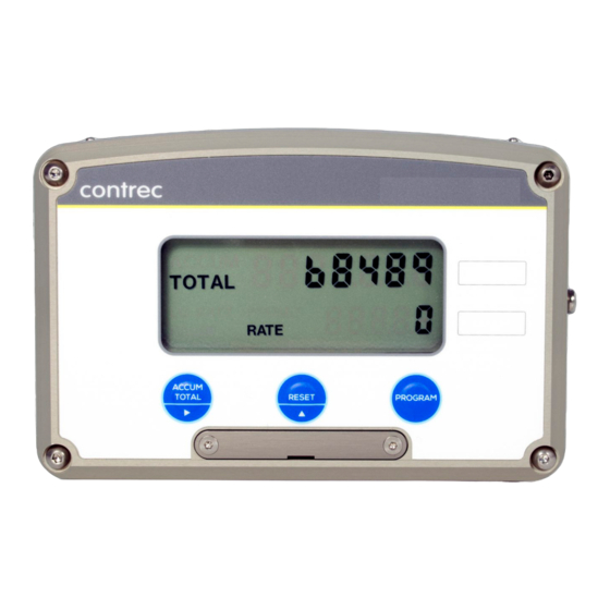
Specification 2. SPECIFICATION General Display: LCD which is continuously powered. Batch Total: 7 digits with 10mm (0.4") high digits. Accumulated Total: Displayed when the ACCUM TOTAL button is pressed. Preset: 5 digits with 8.5mm (0.33") high digits. K-factor: The pulses per unit of measure (e.g. pulses/gallon) is programmable in the range 0.0001 to 999,999. - Page 11 Specification Physical Temperature: Operating temperature: -20°C to 60°C. Dimensions: 98mm (3.9") high x 152mm (6.0") wide x 43mm (1.7") deep (cable glands not included). Protection: Sealed to Nema 4X or IP67 standards. Cable Entry: By cable glands. Material: Polycarbonate and ABS. Wall Mounting: Universal mounting bracket supplied as standard.
-
Page 12: Operation
Operation 3. OPERATION The Model 214Di Batch Controller accepts a frequency or pulse input from a wide range of flowmeters. The instrument is fully programmable with all operating parameters and calculation constants programmable from the front panel. The setup parameters are stored in a non-volatile memory and are retained for at least 10 years in the event of a power loss. - Page 13 Operation Switch Action Display Comments Press 2 "2" 345 Pressing the key will change digit and enables the next digit to be incremented. (The right arrow on the RUN key indicates to change digit.) Press PRESET 22345 Pressing PRESET returns the instrument to the Run mode and batches can now be run.
-
Page 14: Test Mode
Operation ACCUMULATED TOTAL During a batch run, the Accumulated Total can be displayed by pressing the ACCUM TOTAL key. In the non-operational state (i.e. when the batch is complete), the ACCUM TOTAL key also functions as the PRESET key and enables the Preset quantity to be changed. -
Page 15: Batch Operations
Operation 3.3 BATCH OPERATIONS The operation of the Batch Controller is shown below: Batch PAUSE Quantity Reached Stop Run "on" state Output 1 "on" state Output 2 Start Time Prestop Quantity Two Stage Valve Control 3.3.1 Control Outputs The two solid state relay outputs can be set up to control a single valve or a dual valve with slow stop and/or slow start. -
Page 16: Signal Timeout
Operation The process can be stopped at any time by pressing the STOP key, whereby both outputs will immediately switch off. The process can then be aborted and the batcher reset by pressing the STOP key again, or the process continued by pressing the RUN key. -
Page 17: Programming
Programming 4. PROGRAMMING The Model 214Di is fully programmable, with all parameters being stored in memory. The Program Mode can be entered in one of two ways: 1. By removing the lower cover strip (i.e. the dark grey strip along the bottom of the enclosure) and turning it end for end and replacing it. -
Page 18: Program Steps
Programming 4.1 PROGRAM STEPS Step Comment Scaling Factor - whole numbers. Scaling Factor - digits after the decimal point. The Scaling Factor is the pulses per unit of measure (e.g.pulses/litre, pulses/gallon, etc). The Scaling Factor can be programmed in the range of 0.0001 - 999,999. Decimal Point for Total Display. -
Page 19: Example
Programming 4.2 EXAMPLE A flowmeter produces 20.538 pulses per litre and has a maximum flowrate of 150litres/minute. It is required to batch quantities in batches of around 300 litres and to alarm if there is no flow once the batch has started. To increase the accuracy of the batch, a two stage valve will be used and the flow will be slow prior to the end of the batch to enable a more accurate cutoff. -
Page 20: Valve Control And Dc Power
Valve Control and DC Power 5. VALVE CONTROL AND DC POWER The Model 214Di will operate from an external power source between 9- 28VDC and draws no more than 4mA. This enables the instrument to be powered from AC mains adaptors and eliminate the need to run mains voltage in the field. - Page 21 Valve Control and DC Power Power 214D Valve Control 1 Relay 1 Opto- Valve Control 2 Isolated Outputs Relay 2 Relays with DC Coils...
-
Page 22: Battery Backup Version
Note: No low battery warning will be displayed whilst there is external DC power connected. New batteries can be purchased via Contrec or our distributors and replaced in the field without compromising the IS approvals. There are two battery packs in each instrument and care must be taken to replace only one pack at a time so that there is always power connected to the memory. -
Page 23: Flowmeter Input
Flowmeter Input 7. FLOWMETER INPUT The Model 214Di has an input conditioning circuit which will accept signals from most pulse or frequency producing flowmeters. Links on the rear panel enable the input circuit to be configured for different signal types. The input will interface directly to: �... - Page 24 Flowmeter Input +3.3V +3.3V pull-up = 0 uA (PULSE link (link 1) not installed) pull-up = 15 uA (PULSE link, no external power) pull-up = 150 uA (PULSE link, external power) INPUT COMPARATOR LINK 2 Simplified Frequency Input Circuit...
- Page 25 Flowmeter Input 1. Squarewave, CMOS or Pulse Link Settings COIL PULSE Link 1 Link 2 Link 3 Switching threshold voltage is 1.3 volts. 2. Open Collector With 15�A/150�A internal pull up current Link Settings COIL PULSE Link 1 Link 2 Link 3 3.
- Page 26 Flowmeter Input 4. Coils Link Settings COIL PULSE Link 1 Link 2 Link 3 825R input impedance eg. Millivolt signal from paddlewheel or turbine (15mV P-P minimum). Note: If the input has a very high impedance, Link Settings the following link settings should be used: COIL PULSE Link 1...
- Page 27 Flowmeter Input 6. Namur Proximity Switch - External DC Power Link Settings COIL PULSE Link 1 Link 2 Link 3 825R input impedance For IS connections of Namur switches see Section 8.
-
Page 28: Intrinsic Safety Connections
Intrinsic Safety Connections 8. INTRINSIC SAFETY CONNECTIONS When installing the Model 214Di in hazardous areas, the wiring and installation must comply with appropriate installation standards. 8.1 COILS The Model 214Di will connect directly to a turbine flowmeter or paddlewheel with a certified Intrinsically Safe (IS) coil or other certified IS sensor which produce a pulse input provided they do not exceed the following input parameters: Ui = 24V... -
Page 29: Simple Apparatus
Intrinsic Safety Connections 8.2 SIMPLE APPARATUS Devices such as reed switches which can be classed as "simple apparatus", as defined in the CENELEC standards EN60079, can be connected to the Model 214Di without certification. 8.3 NAMUR PROXIMITY SWITCHES Connection to certified Namur proximity switches is permitted as shown on the following page with the following maximum input parameters: Ui = 24V Ii = 20mA... - Page 30 Intrinsic Safety Connections Input...
-
Page 31: Relay Outputs
Intrinsic Safety Connections 8.4 RELAY OUTPUTS The low alarm and high alarm/pulse output can be connected to suitably certified devices providing the circuit is protected with a barrier with the maximum safety parameters: Uo = 28V Io = 93mA Pmax = 0.653W The input capacitance on these terminals is 0.1uF max and the inductance is negligible. - Page 32 Intrinsic Safety Connections...
- Page 33 Installation 9. INSTALLATION 9.1 WALL MOUNTING A wall mounting bracket is supplied with each instrument. Round head screws should be used to attach the bracket to the wall (countersunk screws should not be used). The bracket is mounted first with the tray section at the bottom.
- Page 34 A diagram of the rear panel is shown below: Rear View of 214D Panel Mount Case The cutout for the panel mount version is 142mm (5.6") wide x 88mm (3.5") high.
- Page 35 Installation 9.3.1 REMOVING THE FRONT PANEL - PLASTIC ENCLOSURE The front panel should be removed as follows: 1. Remove the top and bottom cover strips (ie. the dark plastic strip) by levering a screwdriver under one end. 2. Undo the screws retaining the front. Do not remove the screws, they are retained by O-rings.
- Page 36 Installation 9.3.2 REMOVING THE FRONT PANEL - ALUMINIUM ENCLOSURE The front panel should be removed as follows: 1. Unscrew the 4 x socket head screws from each corner of the front panel. 2. The screws are not retained so removed them completely. 3.
- Page 37 Installation 9.4 THE MAIN ELECTRONICS The front section of the housing contains the microprocessor, display and the batteries if fitted. It is possible to adjust the display contrast via a small potentiometer on the board. The Display Contrast is shown below and this can be adjusted for optimum contrast.
- Page 38 Electromagnetic Compatibility as per EMC-Directive 2004/108/EC of the Council of the European Community. 9.7 MAINTENANCE All printed circuit boards must be repaired by Contrec. In the case of a fault, no attempt should be made to repair the board as the intrinsically safe functionality may be impaired.
- Page 39 Installation 35 9.9 INSTRUMENT DIMENSIONS 9.9.1 Aluminium Enclosure 106mm 161mm 47mm 9.9.2 Plastic Enclosure 98mm 151.5mm 43mm...
- Page 40 36 Installation 9.10 TERMINAL DESIGNATIONS All versions Pulse (+) / Coil Input Pulse (-) / Coil Input Output 2 (+) Output 2 (-) Output 1 (+) Output 1 (-) DC Power +9 to 28V DC Power...
- Page 41 Contact your local environmental authority for information regarding disposal or recycling of used batteries, alternatively they can be returned directly to Contrec Ltd. for disposal. Please Contact Contrec Ltd before returning batteries for disposal.
- Page 42 Index 38 Removing the Front Index Panel, 31 Group, 4 Reset Switch, 33 Grounding, 33 Accumulated Total, 1, 6, Scaling Factor, 14, 15 8, 10, 16 Signal Timeout, 12 Input Signal, 19 Simple Apparatus, 25 Installation, 29 Intrinsic Safety, 4, 24 Solenoids, 16, 27 Isolation, 6 Specification, 6...
Need help?
Do you have a question about the 214D and is the answer not in the manual?
Questions and answers