Table of Contents
Advertisement
Quick Links
Advertisement
Table of Contents

Related Manuals for Contrec 114D


Summary of Contents for Contrec 114D
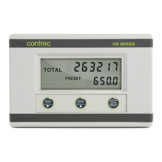
- Page 1 FIELD MOUNTED BATCH CONTROLLER MODEL 114D APRIL 2019 MAN-114D-V1.3...
-
Page 2: Table Of Contents
5. Valve Control and DC Power 6. Battery Backup 7. Flowmeter Input 8. Installation 8.1 Wall Mounting 8.2 Removing the Front Panel 8.3 The Main Electronics 8.4 Wiring 8.5 Maintenance 8.6 Terminal Designations 9. Disposal 9.1 Instrument Disposal 9.2 Battery Disposal Index MAN-114D-V1.3... - Page 3 MAN-114D-V1.3...
-
Page 5: Introduction
– EMC requirements : Residential, Commercial & Light Industry Environment & Industrial Environment. EN61010:2010 Safety requirements for electrical equipment for measurement, control, and laboratory use. In order to comply with these standards, the wiring instructions in Section 9.5 must be adhered to. MAN-114D-V1.3... - Page 6 Note the battery polarity when replacing. Battery Life: 2 years typical. Outputs Outputs: Two solid state relay outputs suitable for driving DC solenoids or external relays. Switching Power: 200mA. 30VDC maximum. Supply Backup: Lithium battery. Isolation: Both outputs are separately isolated via opto- isolators. MAN-114D-V1.3...
-
Page 7: Specification
98mm (3.9") high x 152mm (6.0") wide x 43mm (1.7") deep (cable glands not included). Protection: Sealed to Nema 4X or IP67 standards. Cable Entry: By cable glands. Material: Polycarbonate and ABS. Wall Mounting: Universal mounting bracket supplied as standard. MAN-114D-V1.3... -
Page 8: Front Panel Operation
4 Operation 3. OPERATION The Model 114 Batch Controller accepts a frequency or pulse input from a wide range of flowmeters. The instrument is fully programmable with all operating parameters and calculation constants programmable from the front panel. The setup parameters are stored in a non-volatile memory and are retained for at least 10 years in the event of a power loss. -
Page 9: Operation
"Pause" message being displayed on the screen. Once the process has been interrupted in this way, it can be continued by pressing the RUN key or the process can be aborted by pressing the STOP switch a second time. MAN-114D-V1.3... -
Page 10: Test Mode
By pressing the PROGRAM key, all segments of the display will flash. Note the relay outputs are only operated when external DC power is present. And any batch in progress when test mode is entered is stopped and cannot be resumed. MAN-114D-V1.3... - Page 11 To exit Test Mode, the front panel keys should be pressed and held in the following order: the ACCUM TOTAL key and then the STOP key. MAN-114D-V1.3...
-
Page 12: Batch Operations
8 Operation 3.3 BATCH OPERATIONS The operation of the Batch Controller is shown below: Batch PAUSE Quantity Reached Stop Run "on" state Output 1 "on" state Output 2 Start Time Prestop Quantity Two Stage Valve Control 3.3.1 Control Outputs The two solid state relay outputs can be set up to control a single valve or a dual valve with slow stop and/or slow start. -
Page 13: Signal Timeout
The process can be stopped at any time by pressing the STOP key, whereby both outputs will immediately switch off. The process can then be aborted and the batcher reset by pressing the STOP key again, or the process continued by pressing the RUN key. -
Page 14: Programming
10 Operation 4. PROGRAMMING The Model 114 is fully programmable, with all parameters being stored in memory. The Program Mode can be entered in one of two ways: 1. By removing the lower cover strip (ie. the dark grey strip along the bottom of the enclosure) and turning it end for end and replacing it. -
Page 15: Program Steps
4.1 PROGRAM STEPS Step Comment CAL 01 Scaling Factor - whole numbers. CAL 02 Scaling Factor - digits after the decimal point. The Scaling Factor is the pulses per unit of measure (eg. pulses/litre, pulses/gallon, etc). The Scaling Factor can be programmed in the range of 0.0001 - 999,999. -
Page 16: Example
12 Programming 4.2 EXAMPLE A flowmeter produces 20.538 pulses per litre and has a maximum flowrate of 150 litres/minute. It is required to batch quantities in batches of around 300 litres and to alarm if there is no flow once the batch has started. To increase the accuracy of the batch, a two stage valve will be used and the flow will be slow prior to the end of the batch to enable a more accurate cutoff. -
Page 17: Valve Control And Dc Power
5. VALVE CONTROL AND DC POWER The Model 114 will operate from an external power source between 9-28VDC and draws no more than 4mA. This enables the instrument to be powered from AC mains adaptors and eliminate the need to run mains voltage in the field. As the instrument has an internal battery backup it will power the instrument if DC power is interrupted, but these batteries are not capable of powering the solenoids or sensors if they require external power (see section 6 for further... - Page 18 12 Valve Control & DC Power Relays with DC Coils MAN114D-V1.3...
-
Page 19: Battery Backup
6. BATTERY BACKUP The Model 114 has bettery backup for the instrument if the supply has been interrupted. The lithium battery packs provide sufficient capacity to power the instruments for up to 2 years and the operator is warned of a low power condition by a message on the LCD display. -
Page 20: Flowmeter Input
14 Battery Backup 7. FLOWMETER INPUT The Model 114 has an input conditioning circuit which will accept signals from most pulse or frequency producing flowmeters. Links on the LCD panel enable the input circuit to be configured for different signal types. The input will interface directly to: ... - Page 21 +3.3V +3.3V Ipull-up = 0 uA (PULSE link (link 1) not installed) Ipull-up = 15 uA (PULSE link, no external power) Ipull-up = 150 uA (PULSE link, external power) INPUT COMPARATOR LINK 2 Simplified Frequency Input Circuit MAN114D-V1.3...
- Page 22 18 Flowmeter Input 1. Squarewave, CMOS or Pulse Link Settings COIL PULSE Link 1 Link 2 Link 3 Switching threshold voltage is 1.3 volts. 2. Open Collector With 15A/150A internal pull up current Link Settings COIL PULSE Link 1 Link 2 Link 3 3.
- Page 23 Flowmeter Input 19 Note: For a switch or reed input with contact bounce link DBH can be switched "on" by linking across the two right pins above DBH. This will eliminate the effect of switch bounce while limiting the input frequency to 200Hz. 4.
- Page 24 18 Flowmeter Input 6. Namur Proximity Switch - External DC Power Link Settings COIL PULSE Link 1 Link 2 Link 3 825R input impedance MAN114D-V1.3...
-
Page 25: Installation
8. INSTALLATION 8.1 WALL MOUNTING A wall mounting bracket is supplied with each instrument. Round head screws should be used to attach the bracket to the wall (countersunk screws should not be used). The bracket is mounted first with the tray section at the bottom. The instrument is then mounted on the bracket with two screws as shown below. -
Page 26: Removing The Front Panel
20 Installation 8.2 REMOVING THE FRONT PANEL The front panel should be removed as follows: 1. Remove the top and bottom cover strips (ie. the dark plastic strip) by levering a screwdriver under one end. 2. Undo the screws retaining the front. Do not remove the screws, they are retained by O-rings. -
Page 27: The Main Electronics
Installation 23 8.3 THE MAIN ELECTRONICS The front section of the housing contains the microprocessor, display and the batteries if fitted. It is possible to adjust the display contrast via a small potentiometer on the board. The Display Contrast is shown below and this can be adjusted for optimum contrast. -
Page 28: Wiring
This wiring practice is mandatory in order to comply with the requirements for Electromagnetic Compatibility as per EMC-Directive 2014/30/EU of the Council of the European Community 8.5 MAINTENANCE All printed circuit boards must be repaired by Contrec Ltd. 8.6 TERMINAL DESIGNATIONS All versions Pulse (+) / Coil Input... -
Page 29: Disposal
Contact your local environmental authority for information regarding disposal or recycling of used batteries, alternatively they can be returned directly to Contrec Ltd. for disposal. Please Contact Contrec Ltd. before returning batteries for disposal, Contrec Ltd will not be responsible for any shipping costs incurred. -
Page 30: Index
Index 26 Index Accumulated Total, 1, 2, Reed Switch, 17 4, 6 Relay Output Test, 6 Relays, 12 Removing the Front Panel, 21 Batch Limit, 5, 10, 11 Reset Switch, 22 Batch Operations, 7 Input Signal, 15 Batch Total, 2, 14 Installation, 20 Battery Backup, 2, 12, 14 Isolation, 2...
Need help?
Do you have a question about the 114D and is the answer not in the manual?
Questions and answers