
Related Manuals for ST&G 1324 AP


Summary of Contents for ST&G 1324 AP
- Page 1 Instructions for 1324 AP / AL Stance Flexion 5 Bar Mechanical Knee ST&G USA Corp. Phone: (714) 524-0663 2691 Saturn St. Fax: (714) 364-8113 Brea, CA 92821 www.stngco.com...
-
Page 2: Description And Purpose
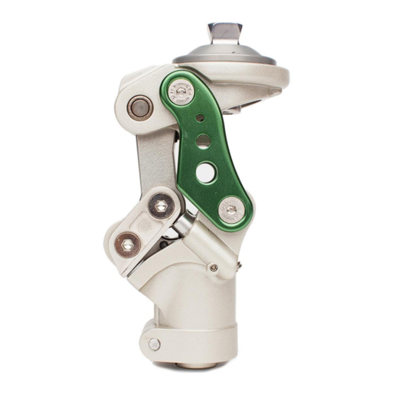
1 Description and purpose These instructions are for use by the practitioner. The 1324 AP/AL knee is to be used exclusively as part of a lower limb prosthesis Recommended for amputees with K2 activity level Weight limit for a user is up to 125 kg / 275 lbs ... - Page 3 2. Construction Principal Parts Frame Aluminum Alloy, Brass, Stainless Steel, Steel Knee head Aluminum Alloy, Stainless Steel Knee control Various materials principally Aluminum Alloy, Stainless Steel, Poly Urethane Copper 1) The First Axis 2) The Second Axis 3) The Third Axis 4) The Fifth Axis 5) The Fourth Axis 6) Knee Head...
-
Page 4: Safety Information
3 Function The flexion control angle up to 12 degree for mimicking normal knee flexion from heel strike to foot flat of a gait cycle Pyramid and Knee Disarticulation mounting options 30mm Distal Tube Clamp Adjustable spring extension assist ... -
Page 5: Maintenance
5 Maintenance Maintenance must be carried out by qualified personnel. Bi-Annual inspection is recommended. Check for visual defects that may affect proper function. A loaner system is available should servicing be required. The wearer should be advised: Any changes in performance of this device must be reported to the Clinician / Practitioner. -
Page 6: Alignment And Set-Up
7 Alignment and Set-Up Users be aware of potential finger trap hazard safety factor Note: 4-bar knees inherently are very stable due to the geometry built into each design. This is commonly referred to as the Instant Knee Center (IKC). The IKC point when doing bench alignment, will fall behind the traditional TKA line that we will reference. - Page 7 b) Ideally, the pylon connecting the knee and foot should end up vertical. Of course, there may be a variance due to the foot alignment recommendations. In this case, the maximum anterior tilt of the pylon should not to exceed 4 degrees, and it may be necessary to utilize offset adapters like the 1222T off set tube clamp c) The weight line should pass through the centerline of the knee in the Coronal or M/L plane (Fig.
- Page 8 8 Knee Adjustment 8.1 Stance Flexion Adjustment NOTE: Stance Flexion set screws have been eliminated. The threaded holes remain, but will not contain a screw. Stance flexion adjustment screws are located on the anterior body of the knee. With 5mm hex wrench, turning both screws clockwise decreases the 5th axis motion, reducing the stance flexion angle.
- Page 9 8.4 Knee Head Tilting Adjusting IMPORTANT! Head Tilt Feature is for fine tuning knee flexion initiation only! It is not for increasing flexion or extension range for alignment. It is possible to decrease knee stability by incorrectly adjusting this feature, which could lead to your patient falling! Loosen the set screw prior to adjusting.
- Page 10 GAIT DEVIATIONS AND ADJUSTMENTS: Excessive Heel Rise: During walking, first try adjusting the knee friction adjustment by turning it up to slow knee flexion initiation during swing. It might be necessary to very slightly increase knee extension assist spring tension by 1/8 turn increments. Increasing extension assist spring tension alone, will not reduce excessive heel rise tendencies.
-
Page 11: Knee Maintenance
9. Knee Maintenance 9.1 Changing Various bumpers: For the knee head leveling bumper, use 2mm hex wrench to loosen the bumper set screw by turning anti- clockwise. Note: Indicate position of the screw prior to removal. Push out the bumper by turning the screw with 5mm hex wrench clockwise. - Page 12 9.2.2 Changing Stance Flexion Bumper Use 4mm hex wrench to loosen the screws of fourth and fifth axes to take out the side bars of stance flexion unit. Please refer to the picture below Pull out opposite side bar along with fourth and fifth axes.
-
Page 13: Technical Specification
9 Technical Specification Operating & Storage Temperature Range: -10˚C to 50˚C ( 14˚F to 122˚F) Weight (Pyramid/Lotus): 766g / 781g Recommended Activity: Maximum User Weight: 125kg (275lbs) Maximum flexion angle: 135 degrees Proximal Alignment attachment: Rotatable Male Pyramid/ Lotus Adapter Distal Alignment attachment: Tube Clamp Tube clamp torque setting:... -
Page 14: Warranty
10 Warranty Warranted for 2 years from the date of invoice by ST&G. The user should be aware that changes or modifications not approved will void the warranty. 11 Liability The manufacturer recommends using the device only under the specified conditions and for the intended purposes. - Page 15 ST&G USA Corporation www.stngco.com e-mail: info@stngco.com 2691 Saturn Street, Brea, CA 92821, USA Tel: 1-714-524-0663 Fax: 1-714-364-8113 1324IFU Rev. B (01-19-18)
Need help?
Do you have a question about the 1324 AP and is the answer not in the manual?
Questions and answers