
Related Manuals for ST&G 1323 AP


Summary of Contents for ST&G 1323 AP
- Page 1 Instructions for 1323 AP / AL Polycentric 5 Bar Pneumatic Knee Joint ST&G USA Corp. Phone: (714) 524-0663 2691 Saturn St. Fax: (714) 364-8113 Brea, CA 92821 www.stngco.com...
-
Page 2: Description And Purpose
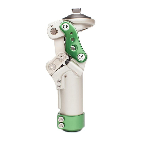
1. Description and purpose These instructions are for use by the practitioner. The 1323AP/AL knee is to be used exclusively as part of a lower limb prosthesis Recommended for amputees with K3. Weight limit for a user is up to 125 kg / 275 lbs ... - Page 3 2. Construction Principal Parts Frame Aluminum Alloy, Brass, Stainless Steel, Steel Knee head Aluminum Alloy, Stainless Steel Knee control Various materials principally Aluminum Alloy, Stainless Steel, Poly Urethane Copper Fig. 1 (a) Side View (b) Frontal View (c) of Knee Unit 1 ) The First Axis 2 ) The Second Axis 3) The Third Axis...
-
Page 4: Safety Information
Function The stance flexion control angle up to 12 degree for mimicking normal knee flexion from heel strike to foot flat of a gait cycle Pyramid and Lotus Adapter’s available Adjustable extension assist Adjustable level of knee head for various users The most light weight in the present market ... -
Page 5: Maintenance
5 Maintenance Maintenance must be carried out by qualified personnel. Bi-Annual inspection is recommended. Check for visual defects that may affect proper function. A loaner system is available should servicing be required. The wearer should be advised: Any changes in performance of this device must be reported to the Clinician / Practitioner. -
Page 6: Alignment And Set-Up
7 Alignment and Set-Up Users be aware of potential finger trap hazard Adjustment range of + 0 to 2mm Fig. 3 Note: 4-bar knees inherently are very stable due to the geometry built into each design. This is commonly referred to as the Instant Knee Center (IKC). The IKC point when doing bench alignment, will fall behind the traditional TKA line that we will reference. - Page 7 anterior tilt of the pylon should not to exceed 4 degrees, and it may be necessary to utilize offset adapters like the 1222T off set tube clamp. In some cases, it may be necessary to slightly adjust the pyramid angle adjustment by loosening the set screw for the adjustment screw and then tuning the angle adjustment screw clockwise.
- Page 8 8 Knee Adjustment 8.1 Flexion / Extension Adjustment Swing Phase Pneumatic setting is pre-set from the factory. Extension or flexion adjustment is only needed if the clinician finds the wearer shows a need for higher or lower walking speeds. Swing Phase Control Adjustment: It is advisable to adjust flexion before extension for optimum walking symmetry.
- Page 9 8.2 Stance Flexion Adjustment NOTE: Stance Flexion set screws have been eliminated. The threaded holes remain, but will not contain a screw. 5mm Stance flexion adjustment screws are located on the anterior body of the knee. Turning both screws clockwise decreases the 5th axis motion, reducing the stance flexion angle.
- Page 10 8.5 Knee Head Tilting Adjusting Loosen the set screw prior to adjusting. After adjusting, tighten set screw. Use 5mm driver and turn the screw: Clockwise (In) to reduce geometric stability of the knee (high front/low rear) and will make knee flexion easier. Anti-clockwise (Out) to increase geometric stability of the knee (low front/high rear) and will make knee flexion more difficult.
-
Page 11: Knee Maintenance
9. Knee Maintenance 9.1 Changing Various bumpers: For the knee head leveling bumper, use 2mm wrench driver to loosen the bumper set screw by turning anti- clockwise. Note: Indicate position of the screw prior to removal. Push out the bumper by turning with a 5mm hex wrench clockwise. - Page 12 9.2.2 Change Stance Flexion Bumper Use 4mm hex wrench to loosen the screws of fourth and fifth axes to take out the side bars of stance flexion unit. Please refer to the picture below – (1324 Knee used for reference only) Pull out another side bar along with fourth and fifth axes after Step “9.2.2”.
-
Page 13: Technical Specification
10 Technical Specification Operating & Storage Temperature Range: -10˚C to 50˚C ( 14˚F to 122˚F) Weight: Pyramid / Lotus 877g / 892g Recommended Activity: Maximum User Weight: 125kg (275lbs) Maximum flexion angle: 135 degrees Proximal Alignment attachment: Rotatable Male Pyramid, or Lotus adapter Distal Alignment attachment: Tube Clamp... -
Page 14: Warranty
10 Warranty Warranted for 2 years from the date of invoice by ST&G. The user should be aware that changes or modifications not approved will void the warranty. 11 Liability The manufacturer recommends using the device only under the specified conditions and for the intended purposes. - Page 15 ST&G USA Corporation www.stngco.com e-mail: info@stngco.com 2691 Saturn Street, Brea, CA 92821, USA Tel: 1-714-524-0663 Fax: 1-714-364-8113 1323IFU Rev. B (01-19-18)
Need help?
Do you have a question about the 1323 AP and is the answer not in the manual?
Questions and answers