
Related Manuals for ST&G L1321 AP


Summary of Contents for ST&G L1321 AP
- Page 1 Instructions for L1321 AP / AL Polycentric 4 Bar Mechanical Manual Locking Knee ST&G USA Corp. Phone: (714) 524-0663 2691 Saturn St. Fax: (714) 364-8113 Brea, CA 92821 www.stngco.com...
-
Page 2: Description And Purpose
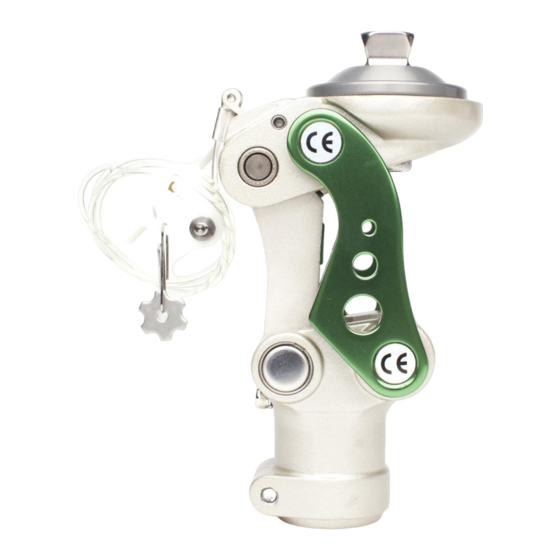
1. Description and purpose Prosthetist instructions. L1321 AP / AL knee is for lower limb prosthesis. Recommended for K1, K2. Weight limit for a user is up to 125kg / 275lbs Ability to lock knee in full extension as part of rehabilitation process. - Page 3 2 Construction Principal Parts: Frame Aluminum Alloy, Brass, Stainless Steel, Steel Knee head Aluminum Alloy, Stainless Steel Knee control Various materials principally Aluminum Alloy, Stainless Steel, Poly Urethane, Copper Fig. 1 (a) Posterior View, (b) Anterior View, c) Lateral View of Knee Unit...
-
Page 4: Exploded View
Exploded View... -
Page 5: Safety Information
3 Function Pyramid and Knee Disarticulation mounting options 30mm Tube Clamp distal mount Adjustable spring extension assist Adjustable friction Manual lock can be disabled 4. Safety Information The Caution symbol highlights safety information which must be followed carefully. -
Page 6: Maintenance
5 Maintenance Maintenance must be carried out by qualified personnel. Bi-Annual inspection is recommended. Check for visual defects that may affect proper function. A loaner system is available should servicing be required. The wearer should be advised: Any changes in performance of this device must be reported to the Clinician / Practitioner. -
Page 7: Alignment And Set-Up
7. Alignment and Set-Up Users be aware of potential finger trap hazard safety factor Note: 4-bar knees inherently are very stable due geometry built into each design. This is commonly referred to as the Instant Knee Center (IKC). The IKC point when doing bench alignment, will fall posterior and anterior to the traditional TKA line that we will reference as Tg (Fig. -
Page 8: Bench Alignment
BENCH ALIGNMENT: a) With prosthesis assembled, taking into account hip flexion contractures, abduction, Line Of Progression, and toe out (Fig.2a), the TKA plumb line should pass through the knee center (center ot proximal/anterior pivot Fig.2a, 2b) and in front of the IKC (red dot). NOTE: Take into account shoe heel height, and add 3mm safety factor. - Page 9 8 Knee Adjustment 8.1 Knee Extension Assist Adjustment Use 6mm hex wrench and turn: Clockwise to increase extension assist. Anti-clockwise to reduce extension assist. After inserting pylon, apply thread locker to the 5mm pinch bolt and torque 12Nm 8.2 Knee Friction Adjustment Use 3mm driver to turn both screws on base of linkage: Clockwise to increase friction.
- Page 10 8.4 Lock Disable Mechanism With the lock lever in the Lock Lever “Unlock” position, with 2.5mm hex wrench, tighten set screw to disable the lock function. Be sure to tighten the screws on both sides so that the lock lever does not spring back to lock position.
- Page 11 Attachment of Lanyard Handle Star Nut: The Star Nut needs to be laminated into the socket. Depending on the nut supplied, the hole should be burnished through, and then: If the Star Nut is not threaded, drill out with 3.3mm drill bit and tap with 4mm tap. If the Star Nut is threaded, chase threaded nut to clean thread with 4mm tap.
- Page 12 Apply Masking tape over the whole area to enable a smooth and relatively flat blended in surface – if the rivet sticks through the tape, that is ok. You want to be sure that the Star Nut is completely covered so it stays in place when the hole is either chased, or drilled and tapped.
- Page 13 9 Maintenance of Knee Unit 9.1 Servicing Extension Stop Bumper Use a small screw driver to pick out the extension stop rubber bumper on knee level adjusting screw. Insert new one into slot.
-
Page 14: Technical Specification
10 Technical Specification Operating & Storage Temperature Range: -10˚C to 50˚C ( 14˚F to 122˚F) Weight (Pyramid / Lotus): 766 g (1lb 11oz) Recommended Activity: K1, K2 Maximum User Weight: 125kg (275lbs) Maximum flexion angle: 135 degrees Proximal Alignment attachment: Rotatable Male Pyramid, Lotus Adapter Distal Alignment attachment:... -
Page 15: Warranty
10 Warranty Warranted for 2 years from the date of invoice by ST&G. The user should be aware that changes or modifications not approved will void the warranty. 11 Liability The manufacturer recommends using the device only under the specified conditions and for the intended purposes. - Page 16 ST&G USA Corporation www.stngco.com e-mail: info@stngco.com 2691 Saturn Street, Brea, CA 92821, USA Tel: 1-714-524-0663 Fax: 1-714-364-8113 L1321IFU Rev. B (01-19-18)
Need help?
Do you have a question about the L1321 AP and is the answer not in the manual?
Questions and answers