Advertisement
Quick Links
EVBUM2614
RSL10-SENSE-GEVK (and
RSL10-SENSE-DB-GEVK)
User Guide
Introduction
The
RSL10−SENSE−GEVK
RSL10−SENSE−DB−GEVK)
compact, node−to−cloud IoT sensor platform that allows
development of various Bluetooth Low Energy based use
cases. Along with the hardware and software, the
RSL10−SENSE−GEVK includes a mobile app to interact
with sensors and actuators. The board features RSL10,
Industry's lowest power Bluetooth
sensors from ON Semiconductor and Bosch. By combining
motion, environmental, ambient light sensing with the
ultra−low power of the Bluetooth 5 Certified RSL10 and
will enable customers to realize a new class of battery
powered static, mobile and wearable smart sensors targeting
consumer and industrial applications in the IoT.
The overall deep sleep consumption of 20 mA results in a
battery life of over 1 year. For further increase in battery life,
software configuration wizard allows flexible timing setup
as discussed in the following sections.
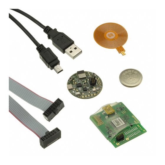
Variants
There are two SKUs of the RSL10 Sensor kit. Both
variants are pre−loaded with an ultra−low power firmware
and include a 3 V CR2032 coin cell and a flexible NFC
antenna.
Figure 1.
RSL10−SENSE−GEVK: Firmware can be flashed via
10−pin needle adapter (e.g. TC2050 from Tag−Connect)
(not included). The 10−pin header for debugger is not
populated on the board.
RSL10−SENSE−DB−GEVK: The "debug" (−DB) version
of the board also includes a low cost Segger debugger
J−Link LITE CortexM and a USB cable. Users can directly
debug/communicate/flash
populated−pin header.
© Semiconductor Components Industries, LLC, 2019
September, 2019 − Rev. 2
(and
is
a
comprehensive,
®
5 SoC and several
the
firmware
over
the
EVAL BOARD USER'S MANUAL
Scope
The board starts functioning as soon as the coin cell is in
place. This document covers the setup, software
architecture, documentation and provides instructions on
downloading firmware to the board. The details regarding
the mobile app and cloud connectivity are not covered in this
document.
Default Configuration
In addition to the RSL10 SiP (System−in−Package), the
following sensors are present on the board.
•
NOA1305, ambient Light sensor
•
N24RF64, NFC EEPROM
•
BME680, environmental sensor (temperature, humidity,
pressure, air quality)
•
BHI160 + BMM150, 3−axis accelerometer, gyroscope,
magnetometer. Together returnabsolute orientation
supported in software
•
INMP522 −> ultra−low power microphone for audio
applications
•
User can insert NFC flexible antenna into dedicated
connector and bend underneath the battery holder for
custom packaging / cases.
1
www.onsemi.com
Figure 2.
Publication Order Number:
EVBUM2614/D
Advertisement

Related Manuals for ON Semiconductor RSL10-SENSE-GEVK


Summary of Contents for ON Semiconductor RSL10-SENSE-GEVK
- Page 1 ® Industry’s lowest power Bluetooth 5 SoC and several sensors from ON Semiconductor and Bosch. By combining motion, environmental, ambient light sensing with the ultra−low power of the Bluetooth 5 Certified RSL10 and will enable customers to realize a new class of battery powered static, mobile and wearable smart sensors targeting consumer and industrial applications in the IoT.
- Page 2 EVBUM2614 Figure 3. Figure 4. Both kits are shipped with the ultra−low power firmware pre−loaded into the boards. Powering the Board To power RSL10−SENSE−GEVK, one has to insert CR2032 (3 V) battery into battery holder located on the bottom side of the board. Figure 5.
- Page 3 RSL10 CMSIS pack Importing CMSIS Packages (see 3.a above) 1. Launch the RSL10 ON Semiconductor IDE 5. CMSIS pack at item 4. is dependent on ARM NOTE: Please import RSL10 CMSIS pack first as the CMSIS pack as well. Please install ARM CMSIS B−IDK CMSIS pack (step 4 in the Prerequisites...
- Page 4 EVBUM2614 Compiling and Flashing of Ultra Low Power Firmware 4. Examples related to RSL10−SENSE−GEVK are highlighted in brackets. Choose the example Custom Service Firmware with Deep Sleep (RSL10−SENSE−GEVK) Figure 8. 5. Right click and copy the project into workspace Figure 9. NOTE: Once the example is copied, it can be viewed under Project Explorer.
- Page 5 EVBUM2614 6. Now user has to build the project as this creates binaries to be flashed to RSL10−SENSE−GEVK. For the sensor board, there are two options: a.) 1 Debug b.) 2 Release – go to hammer icon inside IDE and click Release.
- Page 6 EVBUM2614 7. Once the build is done, the code is ready to be flashed to the RSL10−SENSE−GEVK. a.) Insert the battery into the board. Mandatory step as it creates the voltage reference for SWD logic signals. b.) Connect the low cost Debugger (RSL10−SENSE−DB−GEVK version) / 10−pin needle adapter with J−LINK (RSL10−SENSE−GEVK version)
- Page 7 EVBUM2614 Figure 16. b.) On the Debugger tab, set RSL10 as the device name. Click Debug. Figure 17. 9. For application debugging, confirm perspective switch by clicking Yes. Figure 18. www.onsemi.com...
- Page 8 EVBUM2614 10. The debug session is now launched. Click Resume (F8) to start the target CPU. Green LED briefly flashes. By default, in Release version is no Logging option and terminal doesn’t return useful data. By terminating the session, user closes connection with DBG server.
-
Page 9: Important Note
EVBUM2614 IMPORTANT NOTE: When the board is flashed, Green LED shortly blinks. Board starts BLE advertising only and is visible on the mobile app. When connection with mobile app is not made for next 60s (by default), blue LED blinks and RSL10−SENSE−GEVK goes into deep sleep mode. - Page 10 EVBUM2614 Figure 24. Mobile App Usage 14. When the appropriate board is selected, one can 13. Within the Advertising Stop Timeout interval, choose what sensor data to observe. Below are board is visible on the app screen. depicted all supported sensors and quantities RSL10−SENSE−GEVK is advertising only over taken.
- Page 11 EVBUM2614 Figure 26. Ultra−low Power Firmware Modes • Gas sensor uses too much power and is not suitable for 15. The following are the low power features of above CR2032 battery powered systems. By default, this described firmware: feature is disabled in ultra−low power firmware •...
- Page 12 EVBUM2614 Figure 27. 19. Short term power consumption (100s interval): 22. Right click on the project and build it • Deep Sleep mode: NOTE: If the binaries are not seen, press F5 (refresh) a.) 1.5 s periodic button check b.) Consumption: 18.7 uA @ 3 V •...
- Page 13 EVBUM2614 Figure 31. 24. When the debug session is launched, click on Resume button (F8). Figure 32. Logging/Debugging This is the next step after launching the session. For logging/debugging the downloaded Firmware, either J−Link RTT or Eclipse Console may be used. This section provides instructions for both.
- Page 14 EVBUM2614 Figure 34. 27. RTT prompts you to select the appropriate microcontroller. Select RSL10 and click OK. The serial terminal is ready to use and the events from RSL10 can be observed by clicking the All Terminals Window. Figure 36. Figure 35.
- Page 15 EVBUM2614 28. Console returns the actual values from all sensors assembled on the board Figure 37. Using Eclipse RTT Console 29. Click the Open a Terminal Icon Figure 38. 30. Enter the values shown below and launch the session. The incoming events are printed on the terminal window.
- Page 16 EVBUM2614 Figure 40. Using J−scope for MIC data visualization 32. Launch Segger J−Scope and click on New project Figure 41. 33. When your Eclipse debug session is launched, use existing Session (alternatively you use USB), set Sample rate every 10us and load elf. file (binary) that is located under Eclipse−workspace and Debug folder.
- Page 17 EVBUM2614 Figure 42. 34. J−Scope symbol section opens. Check dmic_value box and hit OK button. Figure 43. 35. Visualization of the audio is started when Red Sampling button is pushed (or F5.) www.onsemi.com...
- Page 18 EVBUM2614 Figure 44. Configuration Setup opening the RTE_... header files using the CMSIS System settings can be configured directly from within the configuration wizard (right click on the header file), CMSIS pack. Each example is equipped with basic system displays the configuration table. Various application configuration that covers three main categories.
- Page 19 EVBUM2614 Figure 45. A brief description on the header files is given in the wizard for various sensors. Figure 46. DOCUMENTATION *.rteconfig The *.rteconfig file lists the software components within Detailed documentation of all functions, code, APIs, the CMSIS pack. To access the components, double click HALs is part of the CMSIS package.
- Page 20 EVBUM2614 Figure 47. Main Help Page The main help page is accessible via Device/BDK, visible for all use cases in *.rteconfig file. It’s further divided into various modules as shown below. Figure 48. www.onsemi.com...
- Page 21 EVBUM2614 Figure 49. Sub−sections may be expanded for further information (Ex: HAL interfaces shown below) Figure 50. CMSIS also provides software timers and applications Figure 51. task manager abstraction layers to enable management of specific tasks and timing within the event kernel. Every example attached to the RSL10−SENSE−GEVK is equipped with addl.
- Page 22 EVBUM2614 Figure 52. Bluetooth is a registered trademark of Bluetooth SIG. www.onsemi.com...
- Page 23 LIMITATIONS OF LIABILITY: ON Semiconductor shall not be liable for any special, consequential, incidental, indirect or punitive damages, including, but not limited to the costs of requalification, delay, loss of profits or goodwill, arising out of or in connection with the board, even if ON Semiconductor is advised of the possibility of such damages. In no event shall ON Semiconductor’s aggregate liability from any obligation arising out of or in connection with the board, under any theory of liability, exceed the purchase price paid for the board, if any.
Need help?
Do you have a question about the RSL10-SENSE-GEVK and is the answer not in the manual?
Questions and answers