Table of Contents
Advertisement
Quick Links
Advertisement
Chapters
Table of Contents

Related Manuals for Omron SYSMAC CV500-BSC11


Summary of Contents for Omron SYSMAC CV500-BSC11
- Page 1 Cat. No. W206-E1-04 SYSMAC CV500-BSC11/21/31/41/51/61 BASIC Units...
- Page 2 CV500-BSC11/21/31/41/51/61 BASIC Units Operation Manual Revised August 2003...
- Page 4 OMRON. No patent liability is assumed with respect to the use of the information contained herein. Moreover, because OMRON is constantly striving to improve its high-quality products, the information contained in this manual is subject to change without notice.
-
Page 6: Table Of Contents
TABLE OF CONTENTS PRECAUTIONS ....... . . 1 Intended Audience . - Page 7 TABLE OF CONTENTS SECTION 8 Troubleshooting and Maintenance ....Troubleshooting ............Maintenance .
- Page 8 About this Manual: This manual describes the installation and operation of the BASIC Unit and includes the sections de- scribed below. The BASIC Unit is a CPU Bus Unit that connects to the CPU bus of a SYSMAC CV-series Programmable Controllers. This Unit can be mounted to the CV500, CV1000, CV2000, or CVM1. Note that this manual is not meant to be a substitute for a manual on BASIC programming.
- Page 9 PRECAUTIONS This section provides general precautions for using the Programmable Controller (PC) and the BASIC Units. The information contained in this section is important for the safe and reliable application of the PC and the BASIC Units. You must read this section and understand the information contained before attempting to set up or operate a PC system.
-
Page 10: Intended Audience
It is extremely important that a PC and all PC Units be used for the specified purpose and under the specified conditions, especially in applications that can directly or indirectly affect human life. You must consult with your OMRON representative before applying a PC System to the above mentioned applications. -
Page 11: Operating Environment Precautions
Application Precautions • The PC outputs may remain ON or OFF due to deposition or burning of the output relays or destruction of the output transistors. As a countermeasure for such problems, external safety measures must be provided to ensure safety in the system. - Page 12 Application Precautions Caution Failure to abide by the following precautions could lead to faulty operation of the PC or the system, or could damage the PC or PC Units. Always heed these pre- cautions. • Fail-safe measures must be taken by the customer to ensure safety in the event of incorrect, missing, or abnormal signals caused by broken signal lines, momentary power interruptions, or other causes.
- Page 13 Application Precautions • When replacing parts, be sure to confirm that the rating of a new part is correct. Not doing so may result in malfunction or burning. • Before touching a Unit, be sure to first touch a grounded metallic object in order to discharge any static built-up.
-
Page 14: Introduction
SECTION 1 Introduction This section provides an introduction to the BASIC Units and describes the general features of the Units. The system, hard- ware, and memory configurations are also provided. Features ..............System Configuration . -
Page 15: Features
Features Section 1-1 Features Interfaces Choose from three different sets of interfaces to connect to the peripheral de- vices required by your system. RS-232C (two) and RS-422 Interfaces CV500-BSC11 (without EEPROM) or CV500-BSC21 (with EEPROM) RS-232C (two) and Centronics Interfaces CV500-BSC31 (without EEPROM) or CV500-BSC41 (with EEPROM) RS-232C (one) and GP-IB Interfaces CV500-BSC51 (without EEPROM) or CV500-BSC61 (with EEPROM) -
Page 16: System Configuration
System Configuration Section 1-2 The other CPU Bus Units are the SYSMAC LINK Unit, SYSMAC NET Link Unit, and SYSMAC BUS/2 Remote I/O Master Unit. Network Communications PC READ and PC WRITE can be used to transfer data to/from other PCs on the same or interconnected networks;... - Page 17 System Configuration Section 1-2 Interface BSC11/BSC21 BSC31/BSC41 BSC51/BSC61 Port 1 Computer (with terminal mode), Computer (with terminal mode), Computer (with terminal mode), (RS-232C) display terminal, printer, display display terminal, printer, display display terminal, printer, display Port 2 (RS-232C) Port 3 Host Link Unit (C500-LK203, (RS-422) C500-LK201-V1, C200H-LK202, and...
- Page 18 System Configuration Section 1-2 either CPU Unit to access any of the BASIC Units via the optical link between the Link Units and/or the CPU Bus connection to the Expansion CPU Rack. BASIC Power BASIC Unit Unit supply Link Unit Link Unit Unit I/O Control...
-
Page 19: Nomenclature And Functions
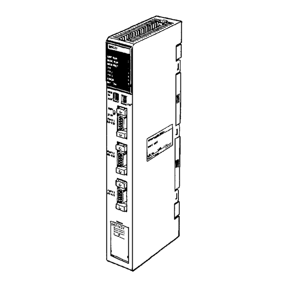
Nomenclature and Functions Section 1-3 Nomenclature and Functions Front Indicators Unit No. switch RUN/STOP switch RS-232C connector (Port 1) RS-232C connector (Port 2) RS-422 connector (Port 3) Battery com- partment where C500-BAT08 is stored. To re- move the cover, slide it down. CV500-BSC11 CV500-BSC31 CV500-BSC51... - Page 20 Nomenclature and Functions Section 1-3 Indicators Indicator Meaning Name Color State UNIT RUN Green Lit after the Unit has been initialized. Lit when the Unit has been reset by the PC during a power interruption, or when an error has occurred in the Unit (when the watchdog timer operates). BASIC RUN Green Lit while the program is executed.
- Page 21 Nomenclature and Functions Section 1-3 Rear View Mounting screw Fixes the BASIC Unit to the Backplane. BASIC Unit connector Connects the BASIC Unit to the Backplane. Mounting screw Fixes the BASIC Unit to the Backplane. 1-3-1 Switch Settings The BASIC Unit is provided with three switches: unit number, run/stop, and DIP switches.
- Page 22 Nomenclature and Functions Section 1-3 Run/Stop Switch Starts or stops the program of the BASIC Unit. This switch is used in combination with a memory switch shown below. The memory switches are contained in the PC and are used to set operating parameters for the BASIC Unit. Refer to 2-2 Memory Switches for details.
- Page 23 Nomenclature and Functions Section 1-3 1-3-2 Hardware Configuration Block Diagram User program EEPROM (source code Battery area) Variable area/ non-volatile variable area System User program program (execution PROM code area) RS-232C RS-232C interface (Port 1) SYSMAC CV-series interface (V25) RS-232C RS-232C interface (Port 2)
- Page 24 Nomenclature and Functions Section 1-3 1-3-3 Memory Configuration The user memory area of the BASIC Unit consists of the following areas: User Program Source Code This area stores the source code of the user program. The machine language Area program is also stored in this area. The user program source code area can be divided into three areas in each of which can be stored an independent program.
-
Page 25: Precautions
Precautions Section 1-4 Precautions Terminals A terminal or personal computer can be connected to the BASIC Unit and run either in terminal mode (TERM) or via communications software. Terminals must be VT-52, VT-100, or equivalents. Programming • Both insert and overwrite programming are available. The writing mode can be set in the memory switches;... - Page 26 Precautions Section 1-4 • Cyclic processing allows specific portions of PC memory to be automatically transferred between the PC and the BASIC Unit. A memory switch is also available to disable cyclic processing to minimize time spent servicing CPU Bus Units. •...
- Page 27 Precautions Section 1-4 • Interrupts from input commands that are awaiting completion will not return to the input command, but to the line following the input command, i.e., the input command will not be completed. Input command variable substitution will not be performed and data may be left in the input buffer.
-
Page 28: Getting Started
SECTION 2 Getting Started This section provides the basic steps to install a BASIC Unit and initiate operation for the first time. It also explains the meth- ods that can be used to start and stop program execution in the BASIC Unit. Installation . -
Page 29: Installation
Installation Section 2-1 Installation This section describes the minimal preparations necessary to set up a BASIC Unit for programming. Refer to Appendix C Hardware Interfaces for information on connecting other types of computers or peripheral devices. Refer to the CV- series PC Installation Guide for details on general PC installation. -
Page 30: Mounting Dimensions
Installation Section 2-1 2-1-2 Mounting Dimensions When installing the BASIC Unit in a control box, determine the depth of the con- trol box giving consideration to the connectors to be connected and the height of the cables. É É É É É... -
Page 31: Switch Settings
Switch Settings Section 2-2 Switch Settings Set the following switches on the BASIC Unit as described below. Details on switch setting are provided in Section 1 Introduction. 1, 2, 3... 1. Set a Unit number in the range of 0 to 15. Do not set the same Unit Number as those of the other CPU Bus Units. -
Page 32: Getting The Terminal Ready
Getting the Terminal Ready Section 2-3 Getting the Terminal Ready To use the BASIC Unit, the CPU Rack and a terminal for developing programs are necessary. The terminal can be any of those illustrated below. A cable that connects the BASIC Unit and the terminal is also necessary. Use CV500-CN228 as the cable connecting the computer (with terminal mode) and BASIC Unit. -
Page 33: Connecting The Terminal
Terminal Preparation Section 2-5 Connecting the Terminal Connect the terminal connecting cable to port 1 on the BASIC Unit, and securely tighten the screws of the cable. The selection of communication ports 1 through 3 used to connect the terminal is specified by the memory switches in the CPU Unit. -
Page 34: Memory Switches
Starting/Stopping Programs Section 2-7 Memory Switches After setting the terminal, turn ON the power to the PC and start the BASIC Unit. If necessary, change the settings of the memory switches. The memory switches are described in 3-2 Memory Switches. Default Settings If the default values are suited to the application, the memory switch settings do not need to be changed. -
Page 35: Starting/Stopping Programs
Starting/Stopping Programs Section 2-7 • Automatic Starting This is to automatically start the program on power application or restarting, and is used to start the program after debugging has been completed. Method Preparation Start Stop From terminal Connect terminal. Input RUN and Input CTRL+X or CTRL+C from Set RUN/STOP switch to RUN. -
Page 36: Memory Areas And Operations
SECTION 3 Memory Areas and Operations This section provides information relating to the memory areas of the BASIC Unit. The memory switch settings and specifica- tions are also provided for the proper operation of the Unit. Memory Areas ............3-1-1 Cyclic Transfer Areas . -
Page 37: Memory Areas
Memory Areas Section 3-1 Memory Areas 3-1-1 Cyclic Transfer Areas Cyclic transfers allow data transfers between the PC’s CPU Unit and BASIC Unit to be synchronized with the cyclic servicing of the CPU Unit. The memory words in the CPU Unit that can be allocated for cyclic transfer include those in I/O Memory, the DM Area, and the EM Area. -
Page 38: Memory Areas
Memory Areas Section 3-1 Direction Word Name Remarks CPU Unit to BASIC System Setup Data written from the Unit CPU Unit to these words can be read to words can be read to N+1 to N+14 User area the BASIC Unit using PC READ ”@SQ..”... - Page 39 Memory Areas Section 3-1 • The memory switch setting to make the above areas cyclic areas is as follows: ESW6-1 = 0082–2000–0001–0010 ESW6-7 = 0082–2010–0001–0010 No. of words Upper address Lower address Area type (0082: DM Area) Note All the values are set in decimal. •...
- Page 40 Memory Areas Section 3-1 Output Status Word (CPU Unit to BASIC Unit) Word n is the first word of the first output area allocated to the BASIC Unit. m = 1500 + unit number x 25 Word Name Function 00 to 14 The contents of the first memory switch word set in the CPU Unit.
-
Page 41: Cpu Bus Link Area
Memory Areas Section 3-1 Word Name Function m + 2 00 to 07 Error Code These bits indicate the contents of the system variable ERR in hexadecimal between 00 and FF. The Error Code is reset to 00 when the program is executed again. Fatal Error Flag This flag turns ON when an error that causes the BASIC Unit to stop has occurred while the program is executed. - Page 42 Memory Areas Section 3-1 All numbers are expressed in BCD: G000 to G004 CPU Unit status System information G000 Minute/second: 00 to 59 Minute Second G001 Date: 01 to 31, Hour: 00 to 23 Date Hour G002 Year: 00 to 99, Month: 01 to12 Year Month G003...
-
Page 43: Data Transfer With The Cpu Unit
Data Transfer with the PC Section 3-2 3-1-4 Restart Bits A Restart Bit is turned ON to restart a BASIC Unit. A001 contains Restart Bits for the CPU Bus Units. To restart a BASIC Unit, turn the corresponding bit of this area ON, and then back OFF again. - Page 44 Data Transfer with the PC Section 3-2 Data Flow The following figure illustrates the areas to/from which data can be written/read by the three data transfer methods described previously, and examples of the BASIC commands used for the transfer. The data transfer method is determined by the suboperand of the PC READ or PC WRITE command.
- Page 45 Data Transfer with the PC Section 3-2 Data Transfer/Reception Timing Data is transferred/received during the CPU Bus Unit service interval of the CPU Unit for both the cyclic and event transfer methods. The cycle at which this serv- icing is executed differs depending on whether the CPU Unit is operating syn- chronously or asynchronously.
-
Page 46: Memory Switches
Memory Switches Section 3-3 Timing (1) to (2) and (3) to (4) If the PC READ or PC WRITE instruction is executed by the BASIC Unit immedi- ately before the event processing period, the CPU Unit transfers/receives the data immediately. Timing (5) to (7) and (6) to (8) If more than one PC READ or PC WRITE instruction is executed before the pro- cessing of one event, any subsequent instructions are kept pending until the... - Page 47 Memory Switches Section 3-3 The memory switches consist of the following parameters. The area for each BASIC Unit occupies 60 words. Each parameter is described in detail in the fol- lowing sections. Note The Extended PC Setup in the CPU Unit, which includes BASIC Unit memory switch settings, can be transferred to and from Memory Cards.
-
Page 48: System Parameters
Memory Switches Section 3-3 3-3-1 System Parameters The system parameters of the memory switch set the basic items related to the operation of the BASIC Unit. The following figure illustrates the bit configuration of the system parameters. Set the bits shaded in this figure to 0. Memory Switch: ESW1 ESW1= (when set from terminal) -
Page 49: Automatic Transfer File Name
Memory Switches Section 3-3 Byte address Program No. b5 b4 Error Message Language Kanji Printer b1, b0: Program No. Setting Function Program 1 Sets program 1 as the user program to be edited on power application or resetting. Program 2 Sets program 2. -
Page 50: Terminal And Printer Ports
Memory Switches Section 3-3 Example: File Name ABC1234.BAS A (41) B (42) C (43) File name is set starting from 1 (31) first bit 2 (32) 3 (33) 4 (34) File name is followed by a period (2E) (2E in hexadecimal) B (42) A (41) Period is followed by file type... -
Page 51: Baud Rates
Memory Switches Section 3-3 Note The default is 0000. Consequently, the following printer and terminal ports are selected: BSC11/BSC21: 0102 (port 1 as terminal port and port 2 as printer port) BSC31/BSC41: 0104 (port 1 as terminal port and Centronics as printer port ) BSC51/BSC61: 0100 (port 1 as terminal port and no printer port) •... -
Page 52: Terminal Specifications
Memory Switches Section 3-3 3-3-5 Terminal Specifications This memory switch sets the model of the terminal and the number of display digits for the terminal connected to the BASIC Unit. Memory Switch: ESW5 ESW5= (when set from terminal) Byte address Number of Display Digits Number of Display Digits This byte sets the number of display digits of the terminal in 2 BCD digits. - Page 53 Memory Switches Section 3-3 A minimum of 3 words is required in the input area to refresh BASIC Unit in- formation. Memory Switch: ESW6 ESW6–1= (when set from terminal) – – – Byte address Byte address Output area 1 8 words Area setting (See the following table.) Output area 2 First word address...
- Page 54 Memory Switches Section 3-3 Example 2 Output Areas: 3 words from CIO 0120 of I/O Memory. 12 words from D24000 of DM Area. 1 Input Area: 2 words from CIO 0032 of I/O Memory. I/O Memory Output area 1 From CIO 0120 3 words I/O Memory From D24000...
-
Page 55: Setting Memory Switches
Setting Memory Switches Section 3-4 3-3-7 GP-IB Setting This parameter sets the operation of the GP-IB interface. The parameter is nec- essary only for the CV500-BSC51 and CV500-BSC61. Memory Switch: ESW7 ESW7= (when set from terminal) +116 +117 Byte address Address of Talker and Listener +117 Sets addresses of talker and listener in BCD (00 to 30). - Page 56 Setting Memory Switches Section 3-4 tes of the first word address (BCD), and 0008 is the number of words (BCD). This setting sets 8 words beginning from word 100 in the I/O memory area as output area 1. Output/Input Area Numbers Output area 1 to 6 1 to 6 Input area 1 to 6...
-
Page 57: Programming Overview
SECTION 4 Programming Overview This section provides an overview of BASIC programming and is not meant to provide a comprehensive explanation of BA- SIC programming. BASIC Syntax and Operations ..........4-1-1 Syntax . -
Page 58: Basic Syntax And Operations
BASIC Syntax and Operations Section 4-1 BASIC Syntax and Operations 4-1-1 Syntax To develop a program in BASIC, an understanding of the syntax and description of BASIC is essential. This section describes some fundamentals of the BASIC syntax and programming techniques. For the details of the BASIC syntax, refer to the BASIC Unit Reference Manual (W207-E1). - Page 59 BASIC Syntax and Operations Section 4-1 Data is classified into character data and numeric data. This also applies to vari- ables, which can be classified into character variables in which character data is stored and numeric variables in which numeric data is stored. Numeric variables are further classified into integer variables and real-number variables.
- Page 60 BASIC Syntax and Operations Section 4-1 Constants The contents (data) of a variable are changed by a substitution or operation. In contrast, a constant, which indicates a value by itself, is used where data does not need to be changed. Like variables, constants are classified into character constants and numeric constants, which are further classified into integer con- stants and real-number constants.
- Page 61 A character expression returns a character string and consists of character vari- ables and character constants coupled with an arithmetic operator (+). Example ”OMRON” + ”Corporation” Relative Expressions A relative expression consists of numeric expressions coupled with a relative operator. The relative operators shown in the following table can be used.
- Page 62 BASIC Syntax and Operations Section 4-1 A OR B XOR (Exclusive OR) A XOR B IMP (Implication) A IMP B EQV (Equivalence) A EQV B BASIC Functions The BASIC Unit supports many functions in addition to ordinary BASIC func- tions. A function is used to perform a predetermined operation on a given argu- ment.
-
Page 63: Basic Operations
BASIC Syntax and Operations Section 4-1 Function Operation Gives size of FILE Gives natural logarithm Returns contents of specified address PEEK Gives random number Searches element of array variable and gives position of character SEARCH Checks sign Gives sine Outputs blank Gives square root Sets column position of screen or printer Gives tangent... - Page 64 BASIC Syntax and Operations Section 4-1 If a character (in this example, X) is delimited by “;”, it is displayed immediately after the character displayed immediately before. If it is delimited by “,”, the character is displayed from the beginning of the next area (one area consists of 14 characters).
- Page 65 BASIC Syntax and Operations Section 4-1 To Output Data to Printer To output data to the printer, use the LPRINT or LPRINT USING command. 10 PARACT 0 20 LPRINT ”BASIC UNIT” 30 END 40 END PARACT Result of execution BASIC UNIT END and STOP Commands Write the END command at the end of the program.
- Page 66 20 INPUT ”NAME”;A$ 30 INPUT ”TEL ”;B$ 40 PRINT ”NAME ”;A$,”TEL ”;B$ 50 END PARACT Result of execution NAME? OMRON TEL ? 123–4567 NAME OMRON TEL 123–4567 As shown above, if a character string specified is enclosed in a pair of double quotation marks (”) before a variable name, the specified character string can...
- Page 67 BASIC Syntax and Operations Section 4-1 Operations To process data through operations, program as follows by using operators and arithmetic functions: To Perform Arithmetic To perform an operation, use arithmetic, relative, and logic operators described Operation earlier. 10 PARACT 0 20 PRINT 10/3 30 PRINT 10%¥3% 40 PRINT 10%/3#...
- Page 68 BASIC Syntax and Operations Section 4-1 Priority of Operators Each operator is assigned priority as shown in the following table. Relative oper- ators are not assigned priority in respect to each other, and are executed in se- quence starting from the left. Priority Operator Operation...
- Page 69 BASIC Syntax and Operations Section 4-1 To Repeat the Same Repeating the same processing is called a loop. Loop processing can be im- Process plemented by using the FOR TO STEP NEXT command. This command re- peatedly executes the processing enclosed between FOR and NEXT. FOR variable name = initial value TO end value STEP increment Processing to be repeated...
- Page 70 BASIC Syntax and Operations Section 4-1 Indefinite loop where relative expression is 1 Example: WHILE 1 to WEND The WHILE WEND command executes the processing enclosed between WHILE and WEND until the condition specified by the relative expression is not satisfied (i.e., becomes false (0)).
- Page 71 BASIC Syntax and Operations Section 4-1 As shown above, by using subroutines the program can be divided into several modules so that it can be easy to see and develop and so that the same process can be executed from different locations. Program Program Task 1...
- Page 72 BASIC Syntax and Operations Section 4-1 Changing Processing To select and execute processing according to the result of a relative expres- According to Conditions sion, the IF THEN ELSE or IF GOTO ELSE command is used. Example IF relative expression THEN line no. ELSE line no.
- Page 73 BASIC Syntax and Operations Section 4-1 If the value specified by the numeric expression is 1, the execution branches to a line number specified first. If the value is 2, the execution branches to a line num- ber specified second. If the value is 3, the execution branches to a line number specified third.
-
Page 74: Writing And Entering Programs
Writing and Entering Programs Section 4-2 Writing and Entering Programs 4-2-1 Preparations When developing or editing program, the uppercase and lowercase characters are not distinguished. The uppercase and lowercase characters are also not distinguished in describ- ing variable names, constant names, and array names. However, they are dis- tinguished in character strings and comments. -
Page 75: Generating Line Numbers
Writing and Entering Programs Section 4-2 4-2-5 Generating Line Numbers Generate line numbers automatically by using the AUTO command. 100 is the start line no. and 5 is the in- AUTO 100,5s ....crement. -
Page 76: Editing Programs
Writing and Entering Programs Section 4-2 4-2-7 Editing Programs To edit a program, use the EDIT command. With this command, read and edit one line of the developed program at a time. Changing Overwrite/Insert To edit programs, it is necessary to write characters over existing characters Mode (overwrite mode), or insert new characters between existing characters (insert mode). -
Page 77: Deleting In Programs
Writing and Entering Programs Section 4-2 2. The program of line 30 is displayed as follows. Move the cursor to the posi- tion of 1 by using the Left Key. EDIT 30 30 FOR I = 1 TO 3 3. Input 2 followed by carriage return. This has edited the program. EDIT 30 30 FOR I = 2 TO 3 Inserting Characters... -
Page 78: Merging Programs
Writing and Entering Programs Section 4-2 2. The line to be copied is displayed as follows, then move the cursor to the position 0 with the Left Key. EDIT 50 50 PRINT I,A 3. Input the number of the line to which line 55 is to be copied. Type 5s 4. -
Page 79: Program Execution And Debugging
Program Execution and Debugging Section 4-3 4-2-13 Keys Operations in Editing The following tables shows the keys that can be used in editing operations. Operation Left Key Moves the cursor to the left. This key is invalid while the cursor is at the beginning of a line. Right Key Moves the cursor to the right. -
Page 80: Execution
Program Execution and Debugging Section 4-3 By using the above commands, the program is debugged. As an example, the following sample program is debugged. 10 PARACT 0 20 A = 3 : B = 4 30 FOR I = 1 TO 3 40 A = A + B 50 PRINT A 60 NEXT I... -
Page 81: Stopping And Resuming Execution
Program Execution and Debugging Section 4-3 4-3-3 Stopping and Resuming Execution STOP Command The STOP command is inserted in the program in advance. When the program is executed and the STOP command is reached, the program is stopped. In the fol- lowing example, the STOP command is placed at line 55. -
Page 82: Step Execution
Program Execution and Debugging Section 4-3 4-3-4 Step Execution After stopping the execution of the program, the program can be executed one line at a time by the STEP command. STEPs 1, 2, 3... 1. First, specify a break point and execute the program. BREAK 20 2. -
Page 83: Saving And Loading Programs
Saving and Loading Programs Section 4-4 [60][40][50] 15 [60][70] Ok TROFF TRON 1 When @ is input, the number of the task under execution can be checked. Saving and Loading Programs The program can be saved to/loaded from the following three devices: EEPROM If the BASIC Unit is provided with EEPROM, all the three programs in the source code area can be saved to or loaded from the EEPROM. -
Page 84: Saving And Loading Via Personal Computers
Saving and Loading Programs Section 4-4 To save the program to the memory card, use the SAVE command. 0 is the device name (0: memory card), SAVE ”0:SAMPLE”s ... and SAMPLE is the file name The contents of the program area currently used are saved to the memory card under a specified file name in text format (in displayed image). - Page 85 Saving and Loading Programs Section 4-4 ******** ******** ******** CPU Unit–BASIC UNIT UPLOAD/DOWNLOAD ******** ******** ******** >>This program uploads/downloads programs created on the CPU Unit from/to the BASIC Unit. *SELECT INPUT ”SELECT L(LOAD(Computer–>BSC))/S(SAVE(BSC–>Computer)) –––”;k$ IF K$=”L” GOTO *PCBSC IF K$=”K” GOTO *BSCPC GOTO *SELECT 200 .
-
Page 86: Data And Files
SECTION 5 Data and Files This section provides information on data management and operations for the BASIC Units. Data Operations ............5-1-1 Handling Numeric Data . -
Page 87: Data Operations
Data Operations Section 5-1 Data Operations 5-1-1 Handling Numeric Data Types of Numeric Data The numeric data the BASIC Unit handles is classified into integers and real numbers, as shown below, and can be expressed in various formats. Octal Integers Decimal Hexadecimal Numeric data... - Page 88 Data Operations Section 5-1 Examples: 9876543210 –1.2345D – 12 345.21 # 12345.6789098 Exponential Format When a number with many digits is handled, writing many 0s is cumbersome and can cause errors in the program. Therefore, the BASIC Unit employs an ex- ponential format to handle a number having many 0s.
- Page 89 Data Operations Section 5-1 Examples: Specifies variable name starting with A DEFINT A ....as integers Specifies variable name starting with B DEFSNG B .
-
Page 90: Handling Character Data
Data Operations Section 5-1 5-1-2 Handling Character Data The BASIC Unit also handles character data in addition to numeric data. When characters are handled as data, various commands and functions that manipu- late character strings in various manners are necessary. The BASIC Unit there- fore supports the following character string manipulation commands and func- tions. - Page 91 The number of characters to be rewritten can be omitted. In this case, the num- ber of characters specified in the left member is assumed. As an example, the following program replaces character string “ABCDE” with “OMRON”. 10 PARACT 0 20 A$ = ”ABCDE”...
- Page 92 Data Operations Section 5-1 5-1-3 Handling Large Quantities of Data When handling a large quantity of data in a program, programming is extremely difficult if separate variable is used for each data item. To facilitate programming, therefore, variables called array variables are used. Array variables can specify more than one data item under one variable name, and are classified into one-di- mensional array variables and multi-dimensional (two-dimensional, three-di- mensional, and so on) variables.
-
Page 93: Handling Time Data
Data Operations Section 5-1 Setting Lower-limit Value of Usually, the subscript of an array starts from 0. However, it can be specified to Subscript start from 1 by using the OPTION BASE command. Example: OPTION BASE 1 DIM A (2,3) Result of execution A(1,1) A(1,2) -
Page 94: Data Input/Output In Program
Data Operations Section 5-1 5-1-5 Data Input/Output in Program To read data by a program, the INPUT command or substitution statement such as A = B is used. However, if a large quantity of data is to be handled or if the input data is known in advance, describing the INPUT command or substitution statement is inefficient and not necessary. -
Page 95: File Operations
File Operations Section 5-2 Result of execution BASIC UNIT 10 16 1990 File Operations 5-2-1 Files A BASIC Unit file manages a cluster of program information and data. Files are classified by the contents or access mode as seen in the following: Data File and Program File Files can be classified by contents into program files and data files. -
Page 96: Manipulating Data Files
File Operations Section 5-2 The sequential access file and random access file each have their own features, seen as follows: Feature Sequential access file Random access file Data access Can only be read from beginning Can be read/written starting from any location (in record units) Data length Can be changed freely Fixed... - Page 97 File Operations Section 5-2 Closing To end inputting/outputting of a file, the file number allocated by the OPEN com- mand must be released by using the CLOSE command to close the file. When the CLOSE command is executed, the data remaining in the buffer is written to the file, so that the file number assigned to that file can be used by other files.
- Page 98 ’Sequential file 90 PARACT 0 100 DIM F$30 110 OPEN ”0: DATA2” FOR OUTPUT AS #1 Opened to output new sequential file A$=” OMRON ” B$=” BASIC ” C$=”UNIT” D$=”BASIC UNIT” Data output to sequential file (data com- WRITE #1,A$,B$ .
- Page 99 File Operations Section 5-2 Operating Random Access File The data length of a sequential access file can be set freely. Data of a random access file is read or written in record units, and the data length is fixed in record units.
- Page 100 File Operations Section 5-2 To write, right-justified, character string UNIT to variable area (buffer) of variable name B$. #1 is the file number, 8 is the record PUT #1,8 ....number (1 through 32767) The data in the buffer is written to the eighth record of the random access file opened under file number #1.
- Page 101 File Operations Section 5-2 Write subroutine 270 *WRT ....280 INPUT ”Record no. (1–999):”;REC% 290 IF REC%>999 THEN ERROR 1 Sets error generation number (ERR = 300 IF REC%<1 THEN ERROR 2 Sets error generation number (ERR = 310 LINE INPUT ”DATA:”;C$ 320 PRINT ”Writes data (Y/[ELSE])”...
-
Page 102: Advanced Programming
SECTION 6 Advanced Programming This section advances further into BASIC programming and provides information on interrupts, multitasking, and machine language for the purposes of advanced programming. Interrupts ............. . . 6-1-1 Defining an Interrupt Service Routine . -
Page 103: Interrupts
Interrupts Section 6-1 Interrupts An interrupt is one means by which a device connected to the BASIC Unit can inform the program that some event has occurred and that some action on the part of the program is required immediately. For example, when a character is received by a communications port, the program must stop whatever it is doing and read the character as soon as possible so that the input buffer does not over- flow. -
Page 104: Interrupt-Related Instructions
Interrupts Section 6-1 6-1-2 Interrupt-related Instructions Interrupts usually occur asynchronously; that is, the program cannot know when an interrupt will occur. However, there may be sections of the program which should not be interrupted. For example, if an interrupt occurs while the program is performing a time-critical calculation, the result of the calculation will be delayed and the program may miss its deadline. -
Page 105: Interrupt Types
Interrupts Section 6-1 Interrupt Programming Example 100 PARACT 0 Define interrupt service routine 110 ON KEY(1) GOSUB 700 Interrupts from numeric key 3 are ignored. Enable interrupts 200 KEY(1) ON ....If numeric key 3 is pressed here, the interrupt service routine will be called. - Page 106 Interrupts Section 6-1 The key pressed is read during the interrupt processing and does not remain in the input buffer. Communications Port Interrupts The ON COM GOSUB statement defines an interrupt routine to be executed when a character is received by a communications port. For example: 100 ON COM(2) GOSUB 1000 110 COM(2) ON When a character is received by communications port 2, the interrupt service...
-
Page 107: Interrupt Processing Details
Interrupts Section 6-1 Error Processing Error processing is slightly different than other interrupt processing. If the BASIC Unit encounters an error (for example, if the program attempts to divide by zero), execution is normally terminated and an error message is printed. If an er- ror-handling “interrupt”... -
Page 108: Multitasking
Multitasking Section 6-2 INTRL contains the line number of the statement that was aborted by the inter- rupt, or 0 if no statement was aborted. Some BASIC Unit instructions take an indefinite amount of time to complete. For example, the INPUT statement causes the Unit to wait until the user has entered a value at the terminal. -
Page 109: Declaration Of Start & End Of Task Program
Multitasking Section 6-2 • The following example shows tasks that transmit and print data, and print re- ceived data. Main Task Prepare data to transmit Start transmit/receive and print tasks Transmit/ Print task Receive Task Wait for end of reception Edit received data Start print task Note Execution of tasks switches after each instruction, even for compound lines. -
Page 110: Starting, Aborting, And Waiting For A Task
Multitasking Section 6-2 The number of WORK bytes is the number of bytes of work area used by the task. The default value is 1024 bytes. The PARACT statement must appear on alone on a line; it cannot be used in a multi-statement line. - Page 111 Multitasking Section 6-2 Waiting for End of Task The task that executed this TWAIT state- 300 TWAIT 1 ....ment will wait for task 1 to exit before continuing.
- Page 112 Multitasking Section 6-2 Example of Program Starting/Ending Task When the RUN command is entered from the terminal or when the BASIC Unit is started by the RUN/STOP switch or by the setting of the automatic start setting area of the memory switch, task 0 is started. Task 0 can then start other tasks with the TASK command.
- Page 113 Multitasking Section 6-2 Switching Tasks When two or more tasks have been started, the BASIC Unit switches between active tasks in round-robin fashion, executing a single statement from each task in turn. In each execution cycle, the next statement from each active task is ex- ecuted in order of its task number.
-
Page 114: Basic Unit Status And Transitions
Multitasking Section 6-2 6-2-4 BASIC Unit Status and Transitions After the BASIC Unit has been started, the internal status of program execution and termination changes as illustrated below. Power ON/restart [ ] indicates command or instruction Automatic start Debug mode Edit mode Source correction Debug... -
Page 115: Inter-Task Communication
Multitasking Section 6-2 6-2-5 Inter-task Communication When a multitasking program is executed, it may be necessary to transfer data between tasks or to synchronize execution of tasks. Transfer of information among tasks is generically called inter-task communication. For example, consider an application which requires the BASIC Unit to receive some information, perform a calculation on the data, and send the result back. - Page 116 Multitasking Section 6-2 Signal-no. must be an integer from 1 to 5 or 10 to 13. Signals 10 through 13 have pre-defined meanings; signals 1 through 5 are available for user definition. The meanings of the pre-defined signals are: Signal Meaning STOP PC watchdog timer error...
- Page 117 Multitasking Section 6-2 Messages Tasks can use messages to communicate when the information to be sent is more complicated than the simple on/off that a signal can indicate. To communicate with messages, the two tasks must first acquire a message number.
-
Page 118: Machine Language
Machine Language Section 6-3 An example in which task 0 stores data in global variables A and B and task 1 performs a calculation using the data is shown below. Global Variable Program Example Declare non-volatile global variable A 10 RDIM A . -
Page 119: Segments And Offsets
Machine Language Section 6-3 6-3-1 Segments and Offsets Memory addresses used by the BASIC Unit consist of two parts: the segment and the offset. Both are 16-bit integers. The actual memory address used by an instruction is calculated by multiplying the segment number by 16 and adding the offset. - Page 120 Machine Language Section 6-3 No address is necessary if you wish to continue entering the program; the BA- SIC Unit automatically increments the location counter appropriately. When you have finished entering the program, type Xs to return to the * prompt. Corrections can be made by deleting with the Backspace Key until the carriage return key is input.
- Page 121 Machine Language Section 6-3 Displaying Memory and The contents of memory can be displayed with the D (Dump) command. For ex- Register Contents ample: Display the contents of memory from *D4000.4008s ....&H4000 to &H4008.
-
Page 122: Examining And Altering Memory With Basic
Machine Language Section 6-3 To check whether the program has been correctly saved or loaded, use the X command immediately after the S or L command. If an error has occurred, an error message (SAVE ERROR or LOAD ERROR) is displayed. -
Page 123: Calling A Machine Language Subroutine
Machine Language Section 6-3 Note that the data read or written by the PEEK and POKE instructions in byte units. 6-3-4 Calling a Machine Language Subroutine To call the machine language subroutine from the BASIC program, use the CALL statement or the USR function. Machine language subroutines that return a val- ue to the BASIC program must be called by the USR function. - Page 124 Machine Language Section 6-3 Here is the machine language portion of the program. It must be loaded in memory at segment &H400, offset &H100 (absolute location &H4100). Make data segment equal to program MOV AW,PS ....segment MOV DS0,AW Get the value to square from &H200...
-
Page 125: Storage Formats
Machine Language Section 6-3 The area of the argument to which the execution result of the machine language program has been given is returned to the BASIC program as the value of the same type. Sample Program The following program inputs two numbers (A% and B%) and calls a machine lan- guage subroutine which stores the larger of the two numbers in C%. - Page 126 Machine Language Section 6-3 Single-precision Floating Single-precision floating point values are stored in four consecutive bytes (32 Point Values bits), in IEEE 32-bit floating point format. Address + 0 Lower byte Address + 1 Address + 2 Upper byte Address + 3 S: sign bit (0: positive, 1: negative) E: exponent (8 bits, offset 127) M: mantissa (23 bits)
- Page 127 Machine Language Section 6-3 Character Strings Character strings are stored with 4 bytes of header information (2 bytes for maxi- mum length and 2 bytes for current length), followed by the characters in the string. A pad byte is appended if necessary so that the number of bytes used is even.
- Page 128 Machine Language Section 6-3 Multi-dimensional Array Multi-dimensional arrays are stored in row-major form; that is, all the elements of one row are stored before the first element of the next row. The diagram below shows the layout of an X×Y array. B(0,0) B(0,1) B(0,2)
-
Page 129: Machine Language Programming Summary
Machine Language Section 6-3 6-3-6 Machine Language Programming Summary To call a machine language program from the BASIC program, use the CALL statement or USR function. Beginning Machine Lan- guage program Return to BASIC RETF program MSET command defines beginning of BASIC program area Defines start address of DEF USR... -
Page 130: Machine Language Monitor Commands
Machine Language Section 6-3 Machine Language Monitor This diagram shows the commands that are used to move between the machine Mode and BASIC Mode language monitor mode and BASIC mode. BASIC mode Machine language mode Line assemble CTRL etc. etc. BASIC pro- Machine language gram... -
Page 131: Pc Communications
PC Communications Section 6-4 PC Communications To transfer data between the CPU Unit and BASIC Unit, the PC READ or PC WRITE command is usually used from the BASIC Unit. However, the CPU Unit can also interrupt the BASIC Unit by executing the SEND(192) or RECV(193) instruction or by using FINS commands. - Page 132 PC Communications Section 6-4 • If m is omitted, 1 is assumed. • Make sure that 1 word of types I, H, O, and B corresponds to 1 variable. • Type A must correspond to 1 variable in format units. •...
- Page 133 PC Communications Section 6-4 4. The PC READ command returns a response (1) to the CPU Unit. CPU Unit Program Application Program (192) SEND 100 ON PC (2) GOSUB System 110 PC (2) ON processing 500 PC READ ”S10H4” ; A(0) 600 RETURN CPU Unit BASIC Unit...
- Page 134 PC Communications Section 6-4 3. Data of the predetermined length is sent from the BASIC Unit with the PC WRITE instruction. The length set for the PC WRITE instruction must be the same as that set for the RECV(193) instruction. 4.
-
Page 135: Peripherals
SECTION 7 Peripherals This section information relating to the use and programming for the peripheral devices. The GB-IB Interface programming is also provided for use with the peripherals. Peripheral Devices ............7-1-1 Using Devices . -
Page 136: Peripheral Devices
Peripheral Devices Section 7-1 Peripheral Devices Various devices such as a terminal, printer, communication port, and network can be connected to the BASIC Unit. These devices can be opened, and data can be read and written, in the same way as a regular file. File buffer Device Data A... - Page 137 Peripheral Devices Section 7-1 Note To establish communication between BASIC Units, specify FIN as the device name in an OPEN command, a network address, node address, and Unit ad- dress, and send or receive data using the PRINT or INPUT statements. Communication Ports The communication ports can be opened by the OPEN statement using device name COM1:, COM2:, or COM3:.
- Page 138 Peripheral Devices Section 7-1 The timing of the communications control parameters is shown in the following diagram. DTR (Out) DSR (In) Signal not check if Signal not check if DS0 is specified DS0 is specified RST (Out) CTS (In) Unlimited wait if CS0 or Unlimited wait if CS0 or nothing is specified.
- Page 139 Peripheral Devices Section 7-1 210 LEDSEG%=FNSEG (64) 500 ’LED ON/OFF/BLINK EXECUTION 510 DEF SEG=LEDSEG%: LO%=0 520 CALL LED% (LO%, LOFF%, LON%, LBLINK%) 530 RETURN 560 END PARACT Note 1. Enter lines 120 through 210 shown above as is (the comment line can be omitted).
-
Page 140: Gp-Ib Programming
GP-IB Programming Section 7-2 440 ’ 450 ’ 460 END PARACT Remarks: • Lines 120 through 210 and 400 through 430 are as shown on the preceding page. • Lines 250 and 260 extinguish all indicators 0 through 7. • Lines 290 and 300 light indicators 1, 3, and 6. •... - Page 141 GP-IB Programming Section 7-2 7-2-1 GP-IB System Configuration In a GP-IB system, all devices are connected in parallel as shown below. Up to 15 interfaces (devices) can be connected to one system. The total length of the connecting cables is 20m or the number of devices con- nected to the same bus ×2m, whichever smaller.
- Page 142 GP-IB Programming Section 7-2 7-2-2 Signal Lines of GP-IB The GP-IB consists of 16 signal lines and 8 ground lines. The signal lines are divided into the following three groups based on their functions. Data Lines (DIO1-DIO8) These 8 lines are the bi-directional data bus. Handshake Lines (DAV, NRFD, NDAC) Signal name Function...
- Page 143 GP-IB Programming Section 7-2 6. After confirming that the NRFD line is high, the talker makes the DAV line low, indicating that the data on the DIO lines is valid. 7. After confirming that the DAV line is low, the listener makes the NRFD line low, indicating that it has started receiving the data.
- Page 144 GP-IB Programming Section 7-2 The interface messages are divided into two types: uni-line messages and mul- ti-line messages. The BASIC Unit automatically transfers an interface message each time it ex- ecutes a statement. The interface message is information necessary for per- forming complicated operations.
- Page 145 GP-IB Programming Section 7-2 Column 0: Address Command Group (ACG) Column 1: Universal Command Group (UCG) Column 2 and 3: Listener Address Group (LAG) Column 4 and 5: Talker Address Group (TAG) Column 6 and 7: Secondary Command Group (SCG) Column 1 through 5: Primary Command Group (PCG) Group Name...
- Page 146 GP-IB Programming Section 7-2 The serial polling is performed with the controller requesting each device to se- quentially transfer a status byte, as follows: DI01 DI08 SPE: Serial poll enable SPD: Serial poll disable TA: Talker address UNT: Untalk STB: Status byte Parallel Polling Parallel polling is a method by which the controller checks the presence or ab- sence of requests from more than one device (up to eight devices) at a time.
- Page 147 GP-IB Programming Section 7-2 Initializing GP-IB Before transmitting data with the GP-IB, it is necessary to initialize the interface bus and measuring instruments. 1, 2, 3... 1. Initialize the GP-IB by making IFC (interface clear) of the interface control bus low: ISET IFC 2.
- Page 148 GP-IB Programming Section 7-2 When the interrupting device has been found, read the data it is trying to send: 24 is the talker address and R is the INPUT@24:R ....data storage variable.
- Page 149 GP-IB Programming Section 7-2 Send program codes to set 2-line resis- 100 PRINT@ 24; ”F3RAN5T1” tor function (F3), auto-range (RA), 5 1/2 digit display (N5), and internal trigger (T1) Clear serial poll register (K) and set 110 PRINT@ 24; ”KM20” .
- Page 150 SECTION 8 Troubleshooting and Maintenance This section provides the error messages and indications required for troubleshooting as well as general maintenance proce- dures for the BASIC Unit. Troubleshooting ............8-1-1 Error Messages .
-
Page 151: Troubleshooting
Troubleshooting Section 8-1 Troubleshooting 8-1-1 Error Messages If an error occurs while a program is being entered or executed, an error mes- sage will be displayed on the terminal and the BASIC Unit will wait for operator input. At this time, an error code corresponding to the error message is set in ERR. - Page 152 Troubleshooting Section 8-1 Error message Error Cause Remedy code Out of memory Memory capacity exceeded; program is Review program and remove too long. unnecessary portions. Memory capacity of compiler area, Use PARACT to increase the work general-purpose memory area, S code area for the task.
- Page 153 Troubleshooting Section 8-1 Error message Error Cause Remedy code Routing error The network specified by a PC READ or PC Correct routing table or specify a WRITE statement was not found in the different network. CPU Unit’s routing table. READ or WRITE PC READ/WRITE command without area Use PC READ and SEND(192), or PC mismatch...
- Page 154 Troubleshooting Section 8-1 Error message Error Cause Remedy code Rename across disks A file cannot be renamed from one drive to Do not attempt to rename files from another. one drive to another. Illegal operation The program attempted to perform a file Check the mode used in the OPEN operation which is not allowed by the file’s statement...
-
Page 155: Error Indication And Status
Space used by variables exceed memory Reduce number of variables. capacity. Compiler error Error in system ROM. Contact your OMRON representative. Not enough memory Out of memory during compilation in RUN Increase program capacity, number of status. variables, or size of variable. -
Page 156: Maintenance
Maintenance Section 8-2 • If the BASIC Unit does not operate at all, contact your OMRON representative. The following errors may occur if the unit number is set incorrectly or if the memory switches cannot be read or written correctly. The BASIC program can- not be executed if any of these errors occur. - Page 157 Maintenance Section 8-2 The guaranteed and typical values for battery life when the power is not supplied to the Unit are shown below. The guaranteed value is based on memory backup at 55°C when the power is not supplied to the Unit. The typical value is based on memory backup at 25°C when the power is not supplied to the Unit Effective life of battery 5 years...
-
Page 158: Inspection
Maintenance Section 8-2 2. While pressing the upper part of the battery compartment cover, slide it down and remove it. 3. Pull out the battery and connector and replace it with a new one. This proce- dure must be completed within 5 minutes. 4. - Page 159 Appendix A Standard Models BASIC Unit Name Specifications Model number BASIC Unit Two RS-232C interfaces, RS-422 interface CV500-BSC11 Two RS-232C interfaces, RS-422 interface, CV500-BSC21 EEPROM Two RS-232C interfaces, Centronics interface CV500-BSC31 Two RS-232C interfaces, Centronics interface, CV500-BSC41 EEPROM RS-232C interface, GP-IB interface CV500-BSC51 RS-232C interface, GP-IB interface, EEPROM CV500-BSC61...
-
Page 160: B Specifications
Appendix B Specifications Ratings Conform to the SYSMAC CV-series Programmable Controllers. Characteristics Item Specification µPD79011 (V25 + internal OS) Operating system Real-time monitor (NEC) Program language Interpreter-type multitasking BASIC and machine language (V25) Number of user tasks 16 (can be executed in parallel) Inter-task communication Message transfer by SEND and RECEIVE instructions. - Page 161 Specifications Appendix B I/O Interfaces RS-232C (Port 1 or Port 2) Item Specification Communication Half duplex Synchronization Start-stop Baud rate 300/600/1,200/2,400/4,800/9,600/19,200 bps Transmission method Point-to-point Transmission distance 15 m max. Interface Conforms to EIA RS-232C RS-422 (Port 3) Item Specification Communication Half duplex Synchronization...
- Page 162 Specifications Appendix B GP-IB Item Specification Communication Half duplex Baud speed Varies depending on device connected Handshake Three-line handshaking Data transmission 8-bit parallel transmission 20 m or number of devices connected to bus × 2 m, whichever is shorter Total cable length Cable length between devices 4 m max.
-
Page 163: C Hardware Interfaces
Plug: XM2A-0901 (OMRON) One plug and one hood are supplied for each port. Connectors other than those on the left cannot be used. Hood: XM2S-0911 (OMRON) or equivalent Recommended Cables AWG28 x 5P IFVV-SB (Fujikura Densen) CO-MA-VV-SB 5P x AWG28 (Hitachi Densen) - Page 164 Hardware Interfaces Appendix C Connection Examples Personal Computers BASIC Unit Personal computer Connector frame Shielded cable Numbers indicate pin numbers. Printers BASIC Unit Printer Connector frame Shielded cable Plasma Displays BASIC Unit Plasma display Connector frame Shielded cable CPU Unit Host Interface/Host Link Unit BASIC Unit Host Interface/Host Link Unit Connector frame...
- Page 165 Receive data Connector Plug: XM2A-0901 (OMRON) One plug and one hood are supplied for port 3. Hood: XM2S-0911 (OMRON) or equivalent Recommended Cables AWG28 x 5P IFVV-SB (Fujikura Densen) CO-MA-VV-SB 5P x AWG28 (Hitachi Densen) Cable length: 500 m max.
- Page 166 Hardware Interfaces Appendix C Wiring the Connector Connect and solder the cable according to the following procedure. Keep the cable length to within the length shown in the following figures. Preparation when Connecting the Shield to FG Cut the cable to the required length. Remove the sheath with a razor.
- Page 167 Hardware Interfaces Appendix C 3. Solder each line. 1 mm Solder iron Thermal contrac- tion tube (Tube F, 1.5 ID, l=10) 4. Slide the heat-shrinking tube over the soldered portion and heat the tube to shrink it into place. Heat shrinking tube Hood Assembly Assemble the connector hood as follows.
- Page 168 Hardware Interfaces Appendix C Connection Example BASIC Unit Host computer RS-232C CV500-BSC11/21 RS-422 Sym- Shield Sym- wire Sym- selec- RS-232C Port 3 tion interface RS-422 circuit Interface Outer connection selection See Note 1. Shield wire Termination resistance Trans- mission AC power supply Recep- 24 V...
- Page 169 Hardware Interfaces Appendix C Connection Example BASIC Unit CV500-BSC11/21 Link Adapter 3G2A9-AL001 Temperature Controller Signal Pin no. Pin no. Signal Signal Pin no. Pin no. RS-422 RS-422 Port 3 interface interface RS-422 Interface Signal See Note. SDB RDA RDB Pin no. Pin no.
- Page 170 Hardware Interfaces Appendix C Connection Example To other Link Adapter 3G2A9-AL001 or BASIC Unit Host BASIC Unit RS-232C computer CV500-BSC11/21 RS-422 Sym- Shield Shield Sym- wire wire selec- RS-422 Port 3 tion 232C interface RS-422 inter- circuit Inter- face face Outer connection selection...
- Page 171 Hardware Interfaces Appendix C Cable Length and Termination Resistance in Multidrop Configurations Use shielded twisted pair cables. Route the cables keeping them separate from other signal lines. Keep the total cable length, including branch lines, to within 500 m. Keep the branch lines to within 10 m. Turn on the termination resistance of the BASIC Units at both ends of the trunk line and that of the Link Adapters.
- Page 172 Hardware Interfaces Appendix C 3G2A9-AL001 Link Adapter Specifications Dimensions Four, 3.5 dia. holes 74.6 58 20.5 Approx. 100 Signals RS-422 Link Adapter 3G2A9-AL001 Applicable Connector Connector: XM2A-0901 Connector cover: XM2S-0901 Three RS-422 connectors are supplied with 3G2A9-AL001.
- Page 173 Hardware Interfaces Appendix C 3G2A9-AL004-(P)E Link Adapter Specifications Dimensions 52.5 10 dia. Approx. 140 Internal Configuration RS-232C BA-422 Symbol Symbol selec- tion circuit Outer con- selection nection Transmis- sion Termination resis- tance Reception AC power supply 24 V Fuse Ground (for the Link Adapter only) Link Adapter 3G2A9-AL004-(P)E...
- Page 174 Hardware Interfaces Appendix C Cable Lengths (max.) Cable unit 3G2A9-AL004-PE 3G2A9-AL004-PE APF (All Plastic optical Fiber) 20 m Not connectable PCF (Plastic Clad optical Fiber) 200 m 800 m Note Be sure to cap all unused optical connectors. Selecting CTS (CS) To keep ON the CTS (clear to send) signal, set to 0 V.
- Page 175 Hardware Interfaces Appendix C Centronics Interface Communication Specifications Conforms to Centronics specifications Pin Configuration Pin no. Abbreviation Name Signal flow STROB Strobe Output DATA 1 Send data Output DATA 2 Send data Output DATA 3 Send data Output DATA 4 Send data Output DATA 5...
- Page 176 Hardware Interfaces Appendix C GP-IB Interface Pin Configuration SHIELD SRQ NDAC DIO4 DIO2 NRFD DIO3 DIO1 DIO7 DIO5 LOGIC DIO8 DIO6 Signal Lines Line Data bus Transmit data DIO 1 (Data Input/Output 1) Example: Address, Command, Measured data, Program data, Display DIO 2 (Data Input/Output 2) data Status data, Status...
- Page 177 Hardware Interfaces Appendix C Recommended Cables Maker Model 408JE-10P5 (50 cm) 408JE-101 (1 m) 408JE-102 (2 m) 408JE-104 (4 m) Honda Tsushin Kogyo ADS-GP24-050 (50 cm) ADS-GP24-100 (1 m) ADS-GP24-200 (2 m) ADS-GP24-300 (3 m) ADS-GP24-400 (4 m) Note Turn off the power to both the GP-IB and BASIC Unit before connecting or disconnecting the GP-IB and BASIC Unit.
-
Page 178: D Program Examples And Reserved Words
..........110 CLS 120 FOR K=0 TO 19 130 LOCATE 20, K:PRINT ”OMRON’s PC is best!” 140 FOR J= 0 TO 200:NEXT J 150 NEXT K 160 LOCATE 20,20:WRITE ”BASIC UNIT is also good.”... - Page 179 Program Examples and Reserved Words Appendix D 190 ’ Calculation result display subroutine 200 *DSPLY ..........Converts character into integer 210 OV%=VAL(V$) .
- Page 180 Program Examples and Reserved Words Appendix D 190 END 200 END PARACT 210 ’**************** 220 ’*MULTI TASK (1)* 230 ’* 240 ’**************** 250 PARACT 1 260 ’Data is received from common memory and message is transferred 270 MESSAGE 0,10 280 RECEIVE 10, MESS$ 290 MESSAGE 1,10 300 PRINT ”Slave task”...
- Page 181 Program Examples and Reserved Words Appendix D Input/Output of Each Port Operation RS-232C Interface Receives RS-232C data by means of an interrupt, and decides whether recep- tion, transmission, or termination is to be performed according to the input data. RS-422 Interface Communicates with the C-series Host Link System, and writes data to the CPU Unit’s data memory on the Host Link System.
- Page 182 Program Examples and Reserved Words Appendix D Branches if interrupt is input to RS-232C 70 ON COM (2) GOSUB *COMPRO ......port Enables port input of RS-232C 80 COM (2) ON...
- Page 183 Program Examples and Reserved Words Appendix D 290 ’ Reception timeout processing 300 *TIMEUP ..........310 ER$=”TIME UP”...
- Page 184 Program Examples and Reserved Words Appendix D PC Communications Operation Writes or reads data to or from the PC connected through a network. Writes data to the memory of the node 1 PC in network 1. The CPU Unit checks whether data has been written, and sends back the data as is.
- Page 185 Program Examples and Reserved Words Appendix D 110 PAUSE Reads data memory 120 PC READ ”#1.1,@D,0,3,S3H4”;DM(0) ....130 FOR I=0 TO 2 IF DM(I) <> R(I) THEN PRINT ”Comparison error”;I Comparison of receive data 150 NEXT I 160 END...
- Page 186 Program Examples and Reserved Words Appendix D Communicating Between BASIC Units Operation Communication is performed between two BASIC Units mounted on the same PC. Data is sent from Unit 0 and Unit 1 processes the data. Configuration BASIC Unit 2 Unit BASIC Power...
- Page 187 Program Examples and Reserved Words Appendix D 130 END 140 ’ 150 *RCV 170 INPUT #1,RCVD$ 180 PRINT ”Received: ”;RCVD$ 190 PRINT #1,RCVD$ 200 RETURN 210 ’ 220 END PARACT Note Start the program for Unit #1 first File Input/Output Operations Sequential File: 1, 2, 3...
- Page 188 Program Examples and Reserved Words Appendix D A$=” OMRON ” B$=” CV500 ” C$=”VERSION 1” D$=”BASIC UNIT” Output data to sequential file (data com- WRITE #1,A$,B$ ........
-
Page 189: G Reserved Words
Program Examples and Reserved Words Appendix D 270 LINE INPUT ”Data: ”;C$ 280 PRINT ”Write the data? (Y/[ELSE])” 290 D$=INKEY$ 300 IF D$=””THEN GOTO 290 310 IF D$<>”Y” AND D$<>”y” THEN RETURN Set data in buffer 320 LSET A$=C$ ......... . Write buffer data 330 PUT #1,REC% . - Page 190 Program Examples and Reserved Words Appendix D KEY ON / OFF / STOP ON TIMER GOSUB RUNr KILL OPEN SAVE LEFT$ OPTION BASE SEARCH OPTION ERASE SEND OPTION LENGTH SENDSIG LINE INPUT PARACT LINE INPUT # PAUSE SIGNAL ON / OFF / STOP LINE INPUT @ PC ON / OFF / STOP LIST / LLIST...
- Page 191 Appendix E BASIC Instructions The instructions of the BASIC Unit are broadly classified into commands, statements, functions, and GP-IB in- structions. Commands can be typed in and executed directly from the console in edit or debug mode. Some commands can also be used as statements.
- Page 192 BASIC Instructions Appendix E Instruction Syntax Purpose Reads BASIC program into current program LOAD LOAD ”file-name” area. Reads BASIC program to current program MERGE MERGE ”file-name” area. Program is merged with any existing program. Sets monitor mode. MSET [address] Sets upper limit of BASIC program area to MSET allocate machine language program area.
- Page 193 BASIC Instructions Appendix E Instruction Syntax Purpose DATA constant [, constant]* Stores numeric and character constants for DATA use by READ statements. Defines function. DEF FN DEF FNfunction-name [(argument [, argument]*)] = function-definition-expression DEF SEG = segment-address Declares segment address. DEG SEG DEF USR [no.] = start-address Defines execution start address of machine...
- Page 194 BASIC Instructions Appendix E Instruction Syntax Purpose LPRINT USING format ; expression Output value of expression using specified LPRINT USING [{, | ; | } [expression]]* format. MESSAGE function, message-no. Allocates and releases message numbers. MESSAGE MID$(character-expression, expression Returns or replaces part of character string MID$ [, expression]) [= character-expression] variable.
- Page 195 BASIC Instructions Appendix E Instruction Syntax Purpose PUT #file-no. [, record-no.] Writes data to random file. RANDOMIZE [expression] Initializes random series. RANDOMIZE RDIM variable-name Declares non-volatile variables. RDIM [(subscript [, subscript]*)] [maximum-number-of-characters] [, variable-name [(subscript [, subscript]*)] [maximum-number-of-characters]]* READ variable [, variable]* Reads data from DATA statement and stores it READ in variable.
- Page 196 BASIC Instructions Appendix E Instruction Syntax Purpose Converts expression into single-precision real CSNG CSNG(expression) number. Converts character string into numeric value. CVI / CVS / CVD CVI(2-character-string) CVS(4-character-string) CVD(8-character-string) DATE$ [= ”year/month/day”] Returns date of internal clock, or sets date. DATE$ Returns true (–1) if file-no.
- Page 197 BASIC Instructions Appendix E Instruction Syntax Purpose Returns a character string with the value of STR$ STR$(expression) expression expressed as a decimal number Returns a string with expression copies of the STRING$ STRING$(expression, {character-string | character-code}) first character of character-expression or character-code.
- Page 198 BASIC Instructions Appendix E Functions Instruction Syntax Purpose Checks the delimiter. IEEE(0) IEEE(0) Checks the initialized status of GP-IB interface. IEEE(1) IEEE(1) Checks the talker and listener status, and IEEE(2) IEEE(2) received interface message. Stores the device status of the device that IEEE(4) IEEE(4) transmits the service request during serial...
- Page 199 Appendix F Machine Language Commands Each of the machine language monitor commands is described in detail on the following pages. In the de- scription, the following syntax is used: • Items in brackets [ ] may be omitted. • An item followed by an asterisk (*) may be repeated. •...
- Page 200 Machine Language Commands Appendix F Example *W4000:12.34.56.78.9As *D4000.4004s 4000–12 34 56 78 9A Command: M Function Moves a specified block of memory to another place in memory. Syntax M destination-address < block-start.block-end Explanation The source block and destination address must be in the same segment. Note Make sure the source and destination areas do not overlap.
- Page 201 Machine Language Commands Appendix F Syntax I[start-address][.end-address] Explanation Disassembles and displays the memory contents between start-address and end-address (example 1). If end-address is omitted, 20 instructions are dis- played (starting at start-address) (example 2). If both start- and end-address are omitted, 20 instructions are displayed starting from the address after the one dis- played immediately before (example 3).
- Page 202 Machine Language Commands Appendix F 2. *SFH4000.41FF.FILE2s Note To save the contents of memory by specifying save destination R, the CVSS is necessary. If the CVSS is not installed, the data are only displayed, and not saved. Command: L Function Loads (reads) a section of memory from a file on the memory card or from the port to which a terminal is connected.
- Page 203 Machine Language Commands Appendix F Command: X Function Displays the result of the previous S, L, or V command. (The S, L, and V com- mands do not display an error code even if an error has occurred while these commands are executed.) The results of executing these commands therefore must be checked by this command.
- Page 204 Machine Language Commands Appendix F The PS (program segment) and program counter (PC) are used and the target address is the specified address plus PS. The initial values of the stack pointers (SP, SS) for MON are set according to MSET.
- Page 205 Machine Language Commands Appendix F Command: K Function Performs addition or subtraction on 4-digit hexadecimal data. Syntax K value + value K value – value Explanation Calculates the sum or difference of the two values. Any carry or borrow is ig- nored.
- Page 206 Machine Language Commands Appendix F Example: File name ABC1234.BAS A (41) B (42) C (43) ..Right-justify file name. 1 (31) 2 (32) 3 (33) 4 (34) ..Place period (&H2E) (2E) after file name.
- Page 207 Machine Language Commands Appendix F 4. *ESW2s ABCDE123.BAS 5. *ESW3s 0000 6. *ESW6–7=0080–0032–0000–0005s 7. *ESW6s 0080 1500 0000 0015 0000 0000 0000 0000 0000 0000 0000 0000 0000 0000 0000 0000 0000 0000 0000 0000 0000 0000 0000 0000 0080 0032 0000 0005 0000 0000 0000 0000 0000 0000 0000 0000 0000 0000 0000 0000...
- Page 208 Machine Language Commands Appendix F Processing Unit To specify whether an instruction should operate on a byte or word, use the BYTE Specifications (Word/Byte) or WORD qualifiers: Examples TEST1 BYTE [IX],CL TEST1 WORD [IY],CL Branch Instructions Labels cannot be used; specify branch addresses. Examples 2000 7502...
- Page 209 Appendix G Reserved Words HEX $ DATA DATE $ ACOS IEEE ALARM DEFDBL DEFINT DEFSNG APPEND DEFSTR INKEY $ INPUT DELIM INPUT $ ASIN DELETE INPUT @ AUTO INSTR EDIT INTR INTRB BASE INTRL BITOFF INTRR ERASE BITON IRESET ISET BREAK ERR2 ERR3...
- Page 210 Reserved Words Appendix G STATUS MERGE RANDOMIZE STEP MESSAGE STOP MID $ RBYTE STR $ MKD $ STRING $ RDIM MKI $ SWAP READ MKS $ RECEIVE MSET TASK RENUM THEN RESTORE NAME TIME $ RESUME TIMER NEXT RETURN RIGHT $ TROFF TRON TWAIT...
-
Page 211: H Controlling Rs-232C Communications Lines
Appendix H Controlling RS-232C Communications Lines RS-232C communications lines are controlled using the OPEN statement as follows: OPEN” COMn: [speed] [, parity] [, data_length] [, stop_bits] [, XON/XOFF] [, RS] [, CSml] [, DS0] [, LF]” AS#file-no. If RS control is designated, the RTS signal will be turned ON when the I/O com- mand is executed and will be turned OFF otherwise. -
Page 212: I Programming With Windows 95 Hyperterminal
Appendix I Programming with Windows 95 HyperTerminal Overview Previously, an FIT10 Terminal Pack or N88-DISK-BASIC was required to program the BASIC Unit. Now, how- ever, it is possible to program using HyperTerminal and other accessories that have been added to the stan- dard Windows 95 package. - Page 213 Key in Ctrl + X at the computer. The following message will be displayed indicating that connection is com- plete. BASIC UNIT Version 1.18 1994/03/25 (C) Copyright OMRON Corporation 1991 Memory Switch Settings for BASIC Unit Set the control method for terminal connection. The backspace key will be enabled by this. Moves to monitor mode MON↵...
- Page 214 Programming with Windows 95 HyperTerminal Appendix I Operation Creating Programs Programs are created using text editors, such as Notepad, and are saved as text. Transferring Programs from the Computer 1, 2, 3... 1. Delete the program currently in the BASIC Unit memory using the NEW command.
-
Page 215: J Setting Memory Switches
Appendix J Setting Memory Switches With BASIC Units, serial port settings and other settings are performed using memory switches. This appendix explains how to make memory switch settings. The following two methods can be used to set memory switches. Explanations for both methods are given below. 1. - Page 216 Setting Memory Switches Appendix J 2. Setting Memory Switches Using Support Software 1. After the Support Software has been connected online to the PC, select “T: CPU SIOU Unit System Setup” from the Communications and CPU Bus Unit Setup Menu. The following screen will be displayed. [CPU SIOU Unit System Setup] Use the PageUp, Page- Down, and Cursor Keys to...
-
Page 217: Glossary
Glossary active controller The device on a general-purpose interface bus that is currently controlling com- munications on the bus. address A number used to identify the location of data or programming instructions in memory or to identify the location of a network or a unit in a network. address command A command sent to a specific address on a general-purpose interface bus. - Page 218 Glossary assembler A program which converts machine-language mnemonics to machine instruc- tions. asynchronous execution Execution of programs and servicing operations in which program execution and servicing are not synchronized with each other. Auxiliary Area A PC data area allocated to flags and control bits. auxiliary bit A bit in the Auxiliary Area.
- Page 219 Glossary central processing unit A device that is capable of storing programs and data, and executing the instruc- tions contained in the programs. In a PC System, the central processing unit ex- ecutes the program, processes I/O signals, communicates with external de- vices, etc.
- Page 220 Glossary CPU Bus Unit A special Unit used with CV-series PCs that mounts to the CPU bus. This con- nection to the CPU bus enables special data links, data transfers, and process- ing. CPU Rack The main Rack in a building-block PC, the CPU Rack contains the CPU, a Power Supply, and other Units.
- Page 221 Glossary destination The location where an instruction places the data on which it is operating, as op- posed to the location from which data is taken for use in the instruction. The loca- tion from which data is taken is called the source. destination line The target of a GOTO or GOSUB statement.
- Page 222 Glossary error generation number A number used to identify an error generated by a program. event (data) transfer A data transfer that is performed in response to an event, e.g., an interrupt sig- nal. event processing Processing that is performed in response to an event, e.g., an interrupt signal. executable statement A statement which causes the BASIC Unit to perform some operation, rather than one which changes the way the BASIC Unit interprets the program.
- Page 223 Glossary general-purpose interface busA bus used to connect various devices to a computer. generation line The line in a program that generates an event, e.g., an interrupt. global variable A variable which can be accessed from any of the tasks in a program. An acronym for Graphic Programming Console.
- Page 224 Glossary I/O Interface Unit A Unit mounted to an Expansion CPU Rack or Expansion I/O Rack to interface the Rack to the CPU Rack. I/O point The place at which an input signal enters the PC System, or at which an output signal leaves the PC System.
- Page 225 Glossary integer constant A numeric value which has a percent sign (%) appended, or an expression con- taining only integer constants. integer variable A variable that can hold an integer value. Intel HEX record Hexadecimal data recorded according to the Intel standard. Intelligent Signal Processor A control-panel interface used to access and control signals.
- Page 226 Glossary line One portion of a BASIC program. A line consists of a line number and one or more statements. link A hardware or software connection formed between two Units. “Link” can refer either to a part of the physical connection between two Units or a software con- nection created to data existing at another location (i.e., data links).
- Page 227 Glossary MS-DOS An operating system in common use on smaller computers. multi-dimensional array An array in which more than one subscript is required to access an element. multidrop configuration A bus configuration in which all devices are connected in series, but across, not through, each device.
- Page 228 Glossary octal A number system where all numbers are expressed in base 8, i.e., numbers are written using only numerals 0 through 7. octal constant An integer constant expressed in octal notation. Octal constants must begin with &, &O, or &o and contain only octal digits (numerals 0 through 7). The status of an input or output when a signal is said not to be present.
- Page 229 Glossary output point The point at which an output leaves the PC System. Output points correspond physically to terminals or connector pins. output signal A signal being sent to an external device. Generally an output signal is said to exist when, for example, a connection point goes from low to high voltage or from a nonconductive to a conductive state.
- Page 230 Glossary program code The representation of a program used internally by the BASIC Unit. Programmable Controller A computerized device that can accept inputs from external devices and gener- ate outputs to external devices according to a program held in memory. Pro- grammable Controllers are used to automate control of external devices.
- Page 231 Glossary record One block or unit of data in a sequential access file. refresh The process of updating output status sent to external devices so that it agrees with the status of output bits held in memory and of updating input bits in memory so that they agree with the status of inputs from external devices.
- Page 232 Glossary RS-232C interface An industry standard for serial communications. RS-422 interface An industry standard for serial communications. RTS signal Request To Send: the BASIC Unit can be programmed to assert this signal when it wishes to send data through a communications port. scan The process used to execute a ladder-diagram program.
- Page 233 The arrangement in which Units in a System are connected. This term refers to the conceptual arrangement and wiring together of all the devices needed to comprise the System. In OMRON terminology, system configuration is used to describe the arrangement and connection of the Units comprising a Control Sys- tem that includes one or more PCs.
- Page 234 A message transferred on the control bus using only one signal line. Unit In OMRON PC terminology, the word Unit is capitalized to indicate any product sold for a PC System. Though most of the names of these products end with the word Unit, not all do, e.g., a Remote Terminal is referred to in a collective sense...
- Page 235 Glossary unit number A number assigned to some Link Units, Special I/O Units, and CPU Bus Units to facilitate identification when assigning words or other operating parameters. universal command A command sent to all devices on a general-purpose interface bus. uploading The process of transferring a program or data from a lower-level or slave com- puter to a higher-level or host computer.
- Page 236 Glossary write-protect A state in which the contents of a storage device can be read but cannot be al- tered.
-
Page 237: Index
Index T, 200 V, 198 W, 195 addresses, GP-IB, 133 X, 199 allocating communications memory, machine language programming, 108 controlling RS-232C lines, 207 message number, 106 PC, 120 program areas, 62 data from the PC, 121 data to the PC, 122 AND, 49 interrupt processing, 120 applications, precautions, xiii... - Page 238 Index debugging, 2 front panel programs, preparations, 67 indicators, 7 nomenclature, 6 deleting, in programs, 65 ports, 6 characters, 65 functions lines, 65 GP-IB, 136 DIP switch, 7 GP-IB list, 194 list, 191 displaying data, 51 returning character strings, 51 ending program, 53 returning numeric values, 50 output data to printer, 53...
- Page 239 Index installation changing, 66 BASIC Unit generating, 63 dimensions, 17 loading mounting, 16 EEPROM, 71 precautions, xiii Floppy Disk, 71 machine language programs, 110 instructions, interrupt-related, 93 memory cards, 71 inter-task communications, 104 signals interrupts, 105 processing routine, 105 program example, 105 machine language, 2, 107 sending, 104 calling a subroutine, 112...
- Page 240 Index precautions, 12 safety, xii printer, ports, 37 printer, ports, memory switch settings, 37 setting procedure, 42 printer ports, 21 system parameters, 35 terminals program areas ports, 37 allocating, 62 specifications, 39 clearing, 62 precautions, 12 messages allocating message number, 106 programming, precautions, 12, 13 program example, 106 programs...
- Page 241 Index switches connecting, 20 DIP switch, 7 getting ready, 19 general settings, 18 ports, 21 RUN/STOP, 7 memory switch settings, 37 settings preparation, 20 DIP switch, 9 specifications, 21 RUN/STOP, 9 memory switch settings, 39 UNIT number, 8 transitions, BASIC Unit, 103 UNIT number setting, 7 troubleshooting, 142 syntax, 46...
-
Page 242: Revision History
Revision History A manual revision code appears as a suffix to the catalog number on the front cover of the manual. Cat. No. W206-E1-04 Revision code The following table outlines the changes made to the manual during each revision. Page numbers refer to the previous version. - Page 243 Revision History Revision code Date Revised content August 2003 Changes were made on the following pages. Page xii: Added information on safety precautions for external circuits. Page xiii: Added ”Power Supply Units” to application precaution. Page 24: Added information on specifying cyclic areas and reading and writ- ing from cyclic areas using the PC READ and PC WRITE instructions.
- Page 244 Wegalaan 67-69, NL-2132 JD Hoofddorp The Netherlands Tel: (31)2356-81-300/Fax: (31)2356-81-388 OMRON ELECTRONICS LLC 1 East Commerce Drive, Schaumburg, IL 60173 U.S.A. Tel: (1)847-843-7900/Fax: (1)847-843-8568 OMRON ASIA PACIFIC PTE. LTD. 83 Clemenceau Avenue, #11-01, UE Square, Singapore 239920 Tel: (65)6835-3011/Fax: (65)6835-2711...
- Page 245 Authorized Distributor: Cat. No. W206-E1-04 Note: Specifications subject to change without notice. Printed in Japan...
- Page 246 Cat. No. W206-E1-04 CV500-BSC11/21/31/41/51/61 BASIC Units OPERATION MANUAL...
- Page 247 WHETHER SUCH CLAIM IS BASED ON CONTRACT, WARRANTY, NEGLIGENCE, OR STRICT LIABILITY. In no event shall the responsibility of OMRON for any act exceed the individual price of the product on which liability is asserted. IN NO EVENT SHALL OMRON BE RESPONSIBLE FOR WARRANTY, REPAIR, OR OTHER CLAIMS...
- Page 248 Application Considerations SUITABILITY FOR USE OMRON shall not be responsible for conformity with any standards, codes, or regulations that apply to the combination of products in the customer's application or use of the products. At the customer's request, OMRON will provide applicable third party certification documents identifying ratings and limitations of use that apply to the products.
- Page 249 Performance data given in this manual is provided as a guide for the user in determining suitability and does not constitute a warranty. It may represent the result of OMRON's test conditions, and the users must correlate it to actual application requirements. Actual performance is subject to the OMRON Warranty and Limitations of Liability.
Need help?
Do you have a question about the SYSMAC CV500-BSC11 and is the answer not in the manual?
Questions and answers