Advertisement
Features
- The latest circuit design permits the instrument to operate with the minimum of influence from earth voltage and dearth resistance of auxiliary earth bars.
- Auxiliary earth resistance and lead wire connection can be self-checked by pressing "BATT.CHECK" button. "OK" lamp lights up when the instrument is ready for accurate earth resistance measurements.
- Low power consumption Only 12V/100mA max.
- Push switch buttons permit smooth operation of the instrument.
- Earth resistance value can be read directly from the scale.
- Simplified measurement can be easily made by pressing th "Simplified Meas." Switch button only. No need to use a shorting wire as terminals P and C and be internally shorted by pressing this switch.
- Battery replacement can be easily made without removing the carrying case.
- Hard plastic carrying case is water resistant and accommodates all accessories.
Specifications
- Measuring ranges:
Earth resistance: 10/100/1000Ω
Earth voltage: 30V AC (5KΩ/V approx.) - Accuracy:
Earth resistance Within ±5% of full scale
Earth voltage Within ±5% of full scale - Measurement system:
Earth resistance
By constant current inverter.
800Hz approx, 2mA
Earth voltage
By rectifier type
5KΩ/V approx, 40~500Hz - Protection levels: EN 61010 – 1; CAT II
- Protection class: class III
- Withstand voltage:
1500V AC for one minute between electrical circuit and housing case. - Self-Check facility:
Lead wire connection to C and P terminals and proper auxiliary earth resistance can be checked by pressing "BATT.CHECK" button. "OK" lamp is illuminated. - Batteries: 8pcs. 1.5V AA battery or equivalent
- Dimensions: 140(L)×140(W)×90(D)mm
- Weight: 800g approx.
- Accessories:
Test leads (red-15m, yellow-10m, green-5m)
Auxiliary earth bars carrying case.
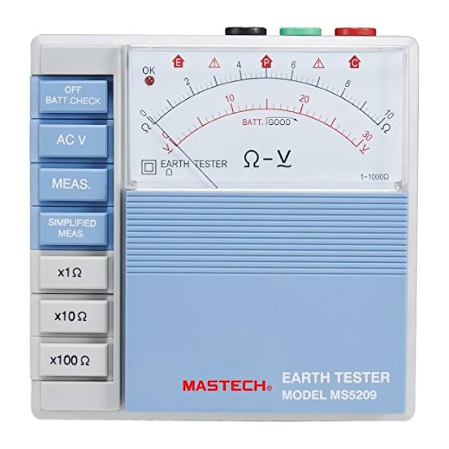
Designations

- OK lamp
- Function switch buttons
- Ohm range switch buttons
- Terminals
- Scale plate
- Panel
How to make measurements
Preparation for measurement

A maximum of 130V DC is present across E and C or E and P terminals during measurement or when "SIMPLIFIED MEAS." Button is pressed. Also, it is present across P and C terminals when "BATT. CHECK" button is pressed. Therefore, never touch these terminals with hand. Always, press "BATT. CHECK" button after use so that all the range and function switch buttons are in off (up) position. Then, release "BATT.CHECK" button.
Meter zero adjust
Check to see if the meter pointer is adjusted exactly to the mechanical zero position of the Ω or V scale. If the pointer is off the zero position in either left or right direction open the panel and turn the zero adjust screw behind the panel with a screwdriver. The panel can be lifted up to 90 degrees by holding both sides as shown below.

Connection of lead wires
As shown in figure below, stick the earth bars P and C deep into the earth.

They should be aligned at an interval of 5m to 10m from the earthed equipment e. Connect the green lead wire to the terminal E of the instrument, yellow wire to terminal P and red wire to terminal C. Make sure to stick the auxiliary earth bars in the moist part of the earth. Give enough water where the auxiliary earth bars have to be stuck into the dry, stony or sandy part of the earth so that it may become moist.
Where it is not possible to drive the auxiliary earth bars into a hard surface such as concrete ground, lay the earth bars there, covet them with a cloth and put water (preferably salt water).This may allow earth resistance measurements. (However, this is not possible with asphalt ground)
NOTE:
When connecting the lead wires, make sure that they are separated. If the measurement is made with the lead wires twisted or in touch with each other it will be affected by the induction of current or voltage.
When the resistance of auxiliary earth bars exceeds 2KΩ it may result in measurement errors. Therefore, be careful in sticking the auxiliary earth bars P1 and C1 into the moist earth. Also, ensure sufficient connections between the respective terminals and lead wires.
Earth voltage measurement of earthed equipment under test
Press the AC V button and check earth voltage. Earth voltage will be indicated on the V scale. When earth voltage is more than 5V it may result in errors in earth resistance measurement. To avoid this make earth resistance measurement after turning off the power source of the equipment under test or reducing earth voltage.
Note:
Even when either of range switch buttons x1Ω, x10Ω and x100Ω is pressed it does not affect earth voltage measurement.
Checking battery voltage & lead wire connection
With "BATT.CHECK" button pressed, the following can be checked simultaneously:
Battery voltage
Battery voltage is sufficient when the meter pointer stays in GOOD area of the battery check scale. If not, replace with the new batteries in accordance with instructions.
Lead wire connection
"OK" lamp lights up when lead wire connection to P and C terminals is good and earth resistance of auxiliary earth is within a limit of tolerance. If it does not illuminate, check for lead wire connection to P and C terminals or lower auxiliary earth resistance to a proper level by changing earth bar location or making the ground moist with water.
Red and yellow lead wires can be checked for possible breakage by shorting the alligator clips at the end of each wire.
NOTE:
There is no need for lead wire connection when battery voltage only is checked. Simply push "BATT.CHECK" button. "OK" lamp will not illuminate.
Earth resistance measurement
Press either of x1Ω,x10Ω and x100Ω range switch buttons. Then press the "MEAS." Button. Multiply the reading by 10 at x10Ω or 100 at x100Ω.
"OK" lamp is on when the instrument is in normal operation. If not, it indicates an excessive earth resistance across C and E terminals that does not permit a normal operation. Recheck for possible contact between each lead wire and earth resistance of auxiliary earth bars in accordance with the instructions. In case "OK" lamp does not illuminate and the meter pointer deflects up full scale despite all preceding checks, possible causes are considered an abnormal condition existing in earthed equipment under test, breakage of connection wires from that equipment or breakage of the green lead wire.
Simplified earth resistance measurement method
4-5-1 This method is recommended where an earth resistance higher than 10 ohms is measured or where it is not possible to drive auxiliary earth bars. An approximate value of earth resistance can be obtained by the two wire system which utilizes existing earthed equipment as shown in Fig.4.
4-5-2 Measurement methods are illustrated in Fig.4.
NOTE:
When making earth resistance measurements using commercial power supply(A),make sure that earth side is connected to P terminal.
4-5-3 Press "AC V" button as outlined in section above for earth voltage measurement of equipment under test and make certain that earth voltage is below 2V. 4-5-4 First press "x10Ω" button and "MEAS." button next Then read earth resistance. When the meter pointer deflects up full scale, press "x100Ω" button. The reading obtained (RE) is and approximate earth resistance value. There is no need for external shorting as P and C terminals are internally shorted. Since measuring current is as low as 2mA, the earth leakage breaker (ELCB) does not trip even if the earth side of the commercial power supply with an ELCB is used.
"OK" lamp is illuminated when the instrument is in normal operation, whether the simplified measurement or normal measurement method is employed.
4-5-5 When the instrument is in working condition, "OK" lamp is illuminated whether the simplified or ordinary measurement is made (This indicates continuity between P plus C terminals and E terminal).However, lead wire connection to P plus C terminals and E terminal). However, lead wire connection to P and C terminals cannot be checked even when "BATT. CHECK" is pressed as the lead wire is not connected to C terminal.
4-5-6 In case of the simplified measurement method where the two terminals only are used, earth resistance "re" of an earthed electrode connecting to P terminal will necessarily be added to a true earth resistance value "REX". Therefore, the earth resistance reading is given as:
RE=REX+re.

If "re" is a known value as follows:
Supposing that RE is 100Ω and an earth resistance to be measured is 100Ω,for example, the true earth resistance value may be expressed as:
REX=(100Ω)-re.
Since re is greater than 0(zero),a true earth resistance may be give as:
REX≤100Ω
In case we measure earth resistance not greater than several tens of ohms we may consider the earth resistance reading obtained as a true value.
- Raise the panel by 90 degrees until it locks.
- Push the "Holder" pressing the upper section of the battery case toward the panel as shown in Fig.5. The battery case will come up.

- Then, pull out the battery case.
- Remove the battery hook on the bottom of the battery case. Empty the battery case and install new batteries.
- Eight pieces of AA battery are used Install them according to the markings on the battery case.
- Fit in the battery hook with polarity in correct position and push back the battery case until it catches the holder.

SAFETY WARNING
- this instrument must be used by a competent, trained person and operated in strict accordance with the instructions.
- my company will not accept liability for any damage or injury caused by misuse or non-compliance with the instructions or safety procedures.
- it is essential to read and understand the safety rules contained in the instructions. they must be observed when using the instrument.
Documents / ResourcesDownload manual
Here you can download full pdf version of manual, it may contain additional safety instructions, warranty information, FCC rules, etc.
Advertisement


Need help?
Do you have a question about the Analog Earth Resistance Tester and is the answer not in the manual?
Questions and answers