
Subscribe to Our Youtube Channel
Related Manuals for Mastech ms5908


Summary of Contents for Mastech ms5908
- Page 1 MS5908 Circuit Analyzer Operation Manual TEST L - N L - E N - E Peak HOLD 12 A 15 A 20 A Z - L Z - N Z - E Ω ASCC GFCI...
-
Page 2: General Instructions
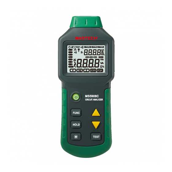
General Instructions Warning This circuit analyzer is a special test device Do not use this instrument without reading, designed for AC low-voltage distribution line quick understanding and following the instructions fault location. With simple operation, accurate in this manual. Read and follow them carefully, measurement and other features, it can detect as well as all warnings and instructions marked multiple problems on a line, such as causing to... - Page 3 FRONT PANEL 1. Input for testing 2. Display 3. Power switch key “ ” 4. Main test item selection key “ ” TEST L - N L - E 5. Data hold key “ ” N - E Peak 12 A 15 A 20 A HOLD Z - L Z - N...
-
Page 4: Menu Operation
Menu Operation The main test items of the analyser are located on the bottom of display, including five test items, namely: voltage (V), voltage drop (Vd), impedance (Z), RCD and GFCI. Press the main test L - N N - E Peak item selection key “... - Page 5 Z - L Z - N Z - E ASCC 12 A 15 A 20 A Impedance (Z): real time display of line connection RCD: real time display of line connection status, status and frequency, and display of the impedance and display current RCD trigger current and trip test results.
-
Page 6: Other Operations
Other Operations: Warning Backlight operation: in powered status, press “ ” Testing earth line conductor impedance, RCD key to light up the backlight. If there is no other key and GFCI will trigger leakage protection device operation for 30 seconds, the backlight will (RCD or GFCI) over the circuit! automatically turn off. -
Page 7: Voltage Measurement
Wiring test Notes: The analyzer can't detect 1. Circuit voltage, i.e. the voltage between two live lines; 2. Combined fault; 3. Reverse connection of earth line and neutral line. The wiring test result will be shown immediately Voltage measurement after the analyzer is plugged to the socket under The normal measured value of phase voltage is test. - Page 8 Fault localization and trouble shooting for voltage Increase neutral problems line conductor, install electrical Fault Voltage to Normal Trouble filter or use Harmonic Measurement Possible earth measurement measurement <2V >2V shooting Item cause interference other methods result result of zero line to reduce the The circuit is Redistribute...
- Page 9 Voltage drop (V ) measurement If the voltage drop exceeds 5%, and during the measurement made near the switchboard, the Dummy load shall be used in the circuit to reading drops constantly and no obvious change measure the load phase voltage and then calculate is found between the two sockets, it indicates that the voltage drop.
- Page 10 According to IEEE, the earth line impedance shall Fault localization and trouble shooting for voltage drop be less than 0.25Ω to ensure the earthing conductor Normal Fault Trouble Measurement Possible measurement measurement to discharge the failure current which threatens all shooting Item cause...
-
Page 11: Residual Current Device (Rcd) Test
Fault localization and trouble shooting Residual current device (RCD) test Normal Fault During the RCD test, the analyzer will generate a Trouble Measurement Possible measurement measurement shooting Item cause low current between live line and earth line by result result means of a fixed resistance, which will affect the No. - Page 12 Fault localization and trouble shooting GFCI test Normal Fault During the GFCI test, the analyzer will generate a low Trouble Measurement Possible measurement measurement shooting Item cause current between live line and earth line by means of a result result fixed resistance, which will affect the current balance Check the circuit and...
-
Page 13: Accuracy Index
Fault localization and trouble shooting Accuracy index Normal Fault Accuracy: ±(% reading + words), one-year guarantee. Trouble Measurement Possible measurement measurement shooting Item cause Reference conditions: result result Ambient temperature: 18°C-28°C Check the circuit and Relative humidity: no more than 80% Install the Fail to be GFCI... -
Page 14: Maintenance
Maintenance Battery installation and replacement: 1) The analyzer is powered by six AAA batteries. 2) Cut off the power and pull out the test line. 3) Unscrew the battery compartment and open the cover. 4) Replace the batteries. 5) Ensure the batteries are installed properly (Do not mismatch polarity) 6) Put back the cover and tighten the screws.
Need help?
Do you have a question about the ms5908 and is the answer not in the manual?
Questions and answers