
Related Manuals for Mastech MS2309


Summary of Contents for Mastech MS2309
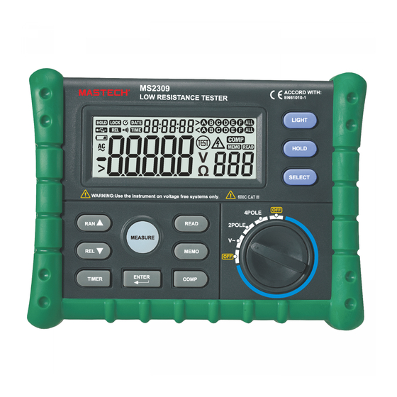
- Page 1 MS2309 Low Resistance Tester HOLD LOCK DATE B C D E TIME B C D E COMP TEST MEMO READ Ω CA T I I I 600 V...
-
Page 2: Table Of Contents
Contents 1. Overview and Safety Information 1. Overview and Safety Information ....................02 Low resistance tester (hereafter known as the 'meter') is designed and manufactured according to the EN61010 safety standard, along with safety requirements for electronic measuring instruments with a over voltage rating of CAT III 600V 2. -
Page 3: Description
2. Description - Always move the rotary switch to the proper position before beginning measurement. This meter is designed for many situations, such as power distribution lines, interior grounding wires, transformer resistance - Do not operate the meter around explosive gas, vapor, or dust. testing, with 2 or 4 wire resistance measurement modes and AC voltage measurement. -
Page 4: Display
2.2 Display HOLD LOCK DATE B C D E TIME B C D E COMP TEST MEMO READ B C D E HOLD LOCK DATE TIME B C D E COMP Ω TEST MEMO READ Ω Display symbols: Symbol Function Symbol Function TEST... -
Page 5: Specifications
3. Specifications 4. Operation Instructions 3.1 Accuracy CAUTION Specified for temperatures of 23°C ±5°, relative humidity <75% Do not attempt to measure more than 600V AC in voltage mode. Accuracy Range To avoid damage to the meter, do not apply voltage to the input terminals when measuring resistance. 2 wire resistance 4Ω, 40Ω, 400Ω... -
Page 6: Voltage Measurement
4.3 Voltage Measurement 4.7 Date and Time Turn the rotary switch to the V~ position. Insert the test leads into the 2W input jacks and connect the leads to the circuit The date or time can be shown at the top of the display. Pressing TIMER will switch between time and date display. under test. -
Page 7: Replacing The Batteries
5. Replacing the Batteries CAUTION Do not attempt to replace the batteries if the tester is wet. Do not open the battery cover during measurement. Always turn the rotary switch to the off position before opening the battery cover. Remove the test leads from the input jacks before opening the battery cover. NOTE Do not mix old and new batteries.
Need help?
Do you have a question about the MS2309 and is the answer not in the manual?
Questions and answers