Table of Contents
Advertisement
Quick Links
Advertisement
Table of Contents

Related Manuals for Mastech MS2301


Summary of Contents for Mastech MS2301
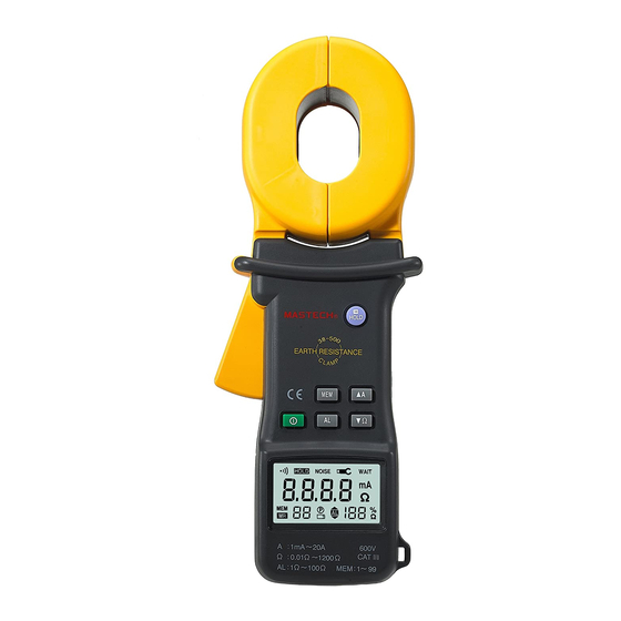
- Page 1 MS2301...
-
Page 2: Table Of Contents
CONTENT I. Safety Rules and Precautions ............2 II. Brief Introduction ................4 III. Model differentiation ................ 5 Ⅳ. Range and Acuracy ................. 5 Ⅴ. Technical Specifications ..............6 Ⅵ. Structure of Meter ................8 Ⅶ. LCD Display ..................8 Ⅷ. -
Page 3: Safety Rules And Precautions
Ⅰ. Safety Rules and Precautions clamp grounding Thank you for purchasing our company's resistance tester . Before using the instrument for the first time, in order to avoid possible electric shock or personal injury, please read and strictly observe the safety rules and be sure to: precautions listed in this manual In any case, use this instrument should pay special attention to... - Page 4 Do not withhold the trigger and do not clamp any wires when turning on the meter After the power is turned on normally, the "OL Ω" symbol is displayed, and the measured object can be clamped. Do not place and store the instrument for a long period of time under conditions of high temperature, humidity, condensation, and direct sunlight.
-
Page 5: Brief Introduction
Because of the reason of this instrument, if it is dangerous to continue using it, it should be immediately stopped and sealed immediately, and it should be handled by a qualified organization. The " " safety warning sign in the instrument and manual must be operated strictly in accordance with the contents of this manual. -
Page 6: Iii. Model Differentiation
At the same time data storage and data upload functions III. Model differentiation Model Resistance Current Range Range 0-20A MS2301 0-1200Ω Ⅳ. Range and Accuracy 1. Ranges and Accuracy of Measurement Mode Range Resolution Accuracy 0.010Ω-0.099Ω... -
Page 7: Ⅴ. Technical Specifications
±(2.5%+5mA) 10.0mA -99.0mA 0.1mA ±(2.5%+10mA) 100mA -300mA Current ±(2.5%+0.1A) 0.30A-2.99A 0.01A ±(2.5%+0.3A) 3.0A-9.9A 0.1A ±(2.5%+0.5A) 10.0A-20.0A 0.1 A Ⅴ. Technical Specifications Functions Ground resistance test, Loop resistance test Ambient Temperature 23℃±5℃,below 75%rh and Humidity DC 6V (4 AA alkaline dry batteries) Power Supply Resistance: 0.01-1200Ω... -
Page 8: Ⅵ.structure Of Meter
Automatically identify interference signals, the "NOISE" Interference Test symbol indicates when the interference current is large Alarm when the measured value exceeds the alarm setting Alarm Function value Real-time display of battery power, reminding timely Battery Voltage charging when battery voltage is low Automatic shut-down Turn off after 5 minutes Power Consumption... -
Page 9: Ⅶ. Lcd Display
1. Clamp Jaw 2. Trigger 3. LCD 4. POWER Key 5. MODE Key 6. AL Alarm Function Key 7. MEM Key 8. SET Key 9. HOLD Key CALIBRATION LOOP:1Ω CALIBRATION LOOP:10Ω VII. LCD Display... - Page 10 (1). Jaw Open Symbol (2). Alarm Symbol (3). Symbol of Greater Than (4). DC AC Symbol (5). Symbol of data access (6). Symbol of data memory (7). Noise signal (8). Data lock symbol (9). Symbol of battery (10). Resistance unit (11).
-
Page 11: Ⅷ. Measuring Principle
pressed, or the jaws have been seriously polluted, and can no longer continue to measure. ⑵. “Er” Boot-strap error symbol, May be pressing trigger or jaw has been opened when the power is turn on. ⑶. Symbol of low battery voltage: when the battery voltage is lower than 5.2V, the symbol shows, it cannot guarantee accuracy of the measurements. -
Page 12: Ⅸ. Operation Method
clamp-type grounding resistance meter is to measure the loop resistance. See below. The jaw section of the clamp meter consists of a voltage coil and a current coil. The voltage coil provides the excitation signal and induces a potential V on the circuit under test. -
Page 13: Battery Voltage Check
Boot, must maintain clamp meter natural resting state, don’t flip Clamp, don’t be imposed outside force on the jaw, otherwise can not guarantee the accuracy of measurement Press the power button to switch on and off. The instrument is automatically calibrated when it is turned on. When the power is turned on, “OLΩ”... - Page 14 is normal. The check ring has two resistances of 1 Ω and 10Ω. After the power-on self test is completed, the large middle digit shows “OLΩ” and resistance measurement can be performed. At this point, withhold the trigger, open the jaws, clamp the circuit under test, and read the resistance value.
-
Page 15: Clock Settings
The circuit of the measured resistance exceeds the lower limit, The number of save groups is 8 and the current time is 12:08 Clock Settings After power on, long press the "SET" button (more than 3 seconds) to enter the clock setting mode. When the time data flashes, it is in the modified state. -
Page 16: Data Storage / Review / Delete
key to lock the current display data, save the data, and press “HOLD” key again to exit lock mode. As shown below: Data Storage / Review / Delete When the measurement is completed after power on, short press "HOLD" key to store data, "MEM" symbol flashes and automatically numbers, if the memory is full, the instrument flashes to display "MEM"... -
Page 17: Ⅹ. Battery Instructions
Ⅹ. Battery Instructions When the voltage drops to 5.2V, the battery symbol " " is displayed. Please replace the battery. Low battery voltage affects measurement accuracy. ⅩI. Field Application 1. Multi-Point Grounding System As for the multi-point grounding system (such as electricity transmission tower grounding... - Page 18 existence of so-called "mutual resistance”, R is not the usual parallel value in the sense of electrical engineering (slightly higher than its IEC parallel output value). But because a tower-grounding hemisphere was much smaller than the distance between the towers, and with a great number of locations after all, R is much smaller than R .
- Page 19 1 + 1 + ..+ 1 + ..+ + ..+ ( N −1) Where: R1、R2、……R are grounding resistances of N grounding bodies. 、R 、……R are the resistances measured with the Meter in the different grounding branches. It is nonlinear equations with N unknown numbers and N equations. It indeed has a definite solution, but it is very difficult to solve the issue artificially, even impossible when N is larger.
- Page 20 However, users need to pay attention to that: in response to the...
- Page 21 number of the grounding bodies mutually linked in your grounding system, it is necessary to measure the same number of the testing values for calculating of the program, not more or less. And the program would output the same number of grounding resistance values.
- Page 22 series resistance from the testing line and two grounding resistances. Where: R is the resistance value measured with the Meter. is the resistance value of the testing line. Meter can measure out the resistance value by connecting the test lines with both ends. So, if the measurement value of the Meter is smaller than the allowable value of the grounding resistance, then the two grounding bodies are qualified for grounding resistance.
- Page 23 Third, have R and R linked up, as shown in the following figure. Use the Meter to get the third reading R In the above three steps, the reading measured in each step is the value of the two series grounding resistance. In this way, we can easily calculate the value of each grounding resistance: From: R1=RA+RB...
-
Page 24: Ⅻ. Accessories
ⅪI. Accessories Earth Tester Battery 5th alkaline battery 4PCS Test Loop User’s Manual 1SET Carrying Case...
Need help?
Do you have a question about the MS2301 and is the answer not in the manual?
Questions and answers