Table of Contents
Advertisement
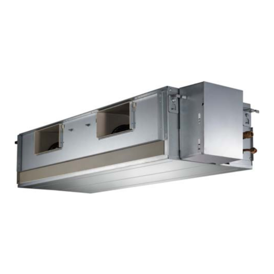
40MBDQ
Ducted Style Ductless System
Sizes 09 to 58
Fig. 1 − Sizes 09−48
Fig. 2 − Size 58
NOTES:
Read the entire instruction manual before starting the
installation.
Images are for illustration purposes only. Actual models may
differ slightly.
Installation Instructions
TABLE OF CONTENTS
. . . . . . . . . . . . . . . . . . . . . . . . . . . . . . . . . . . . . . .
. . . . . . . . . . . . . . . . . . . . . . . . . . . . . . . . . . . . . . . . . . .
. . . . . . . . . . . . . . . . . . . . . . . . . . . . . . . . . . . . . .
. . . . . . . . . . . . . . . . . . . . . . . . . . . . . . .
. . . . . . . . . . . . . . . . . . . . . . . . . . . . . . . . . . . . . . . .
. . . . . . . . . . . . . . . . . . . . . . . . . . . . . .
. . . . . . . . . . . . . . . . . . . . . . . . .
. . . . . . . . . . . . . . . . . . . . . . . . . . .
. . . . . . . . . . . . . . . . . . . . . . .
. . . . . . . . . . . . . . . . . . . . . .
. . . . . . . . . .
. . . . . . . . . . . . . . . . . . . . . . .
. . . . . . . . . . . . . . . . . . . . .
. . . . . . . . . . . . . . . . . . . . . . . . .
PAGE
2
3
4
4
5
7
7
8
8
12
21
21
24
25
Advertisement
Table of Contents


Need help?
Do you have a question about the 40MBDQ09 3 Series and is the answer not in the manual?
Questions and answers