Carrier 40MB*F Installation Instructions Manual
40mb*f
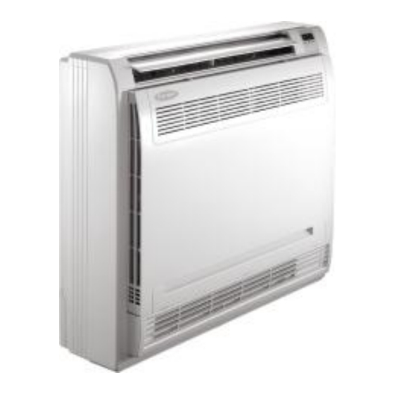
floor console ductless split system
Hide thumbs
Also See for 40MB*F:
- Owner's manual (26 pages) ,
- Installation instructions manual (18 pages) ,
- Service manual (76 pages)

Related Manuals for Carrier 40MB*F


Summary of Contents for Carrier 40MB*F
-
Page 1: Table Of Contents
40MB*F Floor Console Ductless Split System Sizes 09 to 12 Installation Instructions TABLE OF CONTENTS PAGE SAFETY CONSIDERATIONS SYSTEM REQUIREMENTS MODEL NUMBER NOMENCLATURE PRECAUTIONS INSTALLATION INFORMATION ACCESSORIES INSPECTING AND HANDLING THE UNIT INDOOR UNIT INSTALLATION OUTDOOR UNIT INSTALLATION INSTALL THE CONNECTING PIPE... -
Page 3: Model Number Nomenclature
If used as MULTI unit, please refer to the Installation & operation manuals packed with outdoor unit. Model Numbers Volt- Ph @ Indoor Model Unit Tons Unit Btuh 60Hz Number 0.75 9,000 208/230-1 40MBQB09F--3 12,000 208/230-1 40MBQB12F--3 Model number Nomenclature Digit 12 indicates voltage 1 = 115/l/60 3 = 208-230-1-60Hz... -
Page 4: Precautions
1. PRECAUTIONS Install the unit according to this installation instructions found in this document. If installation is defective, it will cause water leakage, electrical shock or fire. Be sure to comply with the local, national and international laws and regulations. When installing the unit in a small space, take measures to prevent refrigerant concentration from exceeding Read "PRECAUTIONS"... -
Page 5: Installation Information
If the refrigerant leaks during installation, ventilate the The appliance must be installed in accordance with area immediately. national wiring regulations. Toxic gas may be produced if the refrigerant enters into the area and comes in contact with fire. Do not operate your air conditioner in a wet room such as a bathroom or laundry room. -
Page 6: Accessories
3. ACCESSORIES Please check whether the following fittings are in scope. If there are some spare fittings , please restore them carefully. Table 3-1 NAME SHAPE QUANTITY Installation fittings 1.Hook 2. Remote controller 3. Frame Remote controller and its Frame 4. -
Page 7: Inspecting And Handling The Unit
4. INSPECTING AND HANDLING THE UNIT At delivery, the package should be checked and any damage should be reported immediately to the service agent. 27.6in/700mm 8.3in/210mm When handling the unit, take into account the following: Fragile, handle the unit with care. Keep the unit upright in order to avoid compressor damage. -
Page 8: Outdoor Unit Installation
6. OUTDOOR UNIT INSTALLATION 6.1 Installation Place The outdoor unit should be installed in the location that meets the following requiements: There is enough room for installation and maintenance. The air outlet and the air inlet are not impeded, and can not be reached by strong wind. -
Page 9: Install The Connecting Pipe
Side air outlet outdoor unit 7. INSTALL THE CONNECTING PIPE (Wall or obstacle) Check whether the height drop between the indoor unit and outdoor unit, the length of refrigerant pipe, and the number of the bends meet the following requirements: Air inlet >11.8in/ 30cm... - Page 10 How to take indoor unit apart to connect the pipes Open the front panel Slide the two stoppers on the left and right sides inword until they click .(Refer to Fig.7-1) Fig.7-3 How to take outdoor unit apart to connect the pipes Remove the water tray (Refer to Fig.7-4)
- Page 11 Table 7-3 Connect the indoor unit first, then the outdoor unit. Tightening torque N M (Turn clockwise to close) Stop Bend the tubing in the proper way. Mainte- Valve size Shaft (valve body) (Valve lid) nance nut Bend the pipe with thumb Ø1/4in/6.35 Hexagonal 5.4~6.6...
-
Page 12: Connect The Drain Pipe
8. CONNECT THE DRAIN PIPE Manifold valve Multi-meter Pressure meter Install the drainpipe of the indoor unit -2.5ftHg/-76cmHg The outlet has PTI screw thread, Please use sealing materials Hi-lever Lo-lever and pipe sheath(fitting) when connecting PVC pipes. Charge hose Charge hose Vacuum pump CAUTION Fig.7-11... -
Page 13: Wiring
For power details of the air conditioner refer to the rating plate of the product. If you have any questions, contact your local dealer. Connect the cable The base pan hole Seal Drain joint of outdoor unit Rotate the installation bearer of the sensing device to the other side, and then take off the cover of electrical box. -
Page 14: Test Operation
10. TEST OPERATION Connect the connective cables to the terminals as identified with their respective matched numbers on the terminal block of the indoor and outdoor units. The test operation must be performed after the entire installation has been completed. Re-install the Indoor unit and outdoor unit Please confirm the following points before the test operation: The Specification of Power... -
Page 15: Outdoor Unit
The Specification of Power Table 9-2 12000Btu/h 18000Btu/h 16000~ TYPE (Cooling & Heating) (Cooling & Heating) PHASE 1-PHASE 1-PHASE POWER FREQUENCY AND VOLT 208-230V~, 50Hz/60Hz 208-230V~, 50Hz/60Hz CIRCUIT BREAKER/FUSE 20/16 20/16 (sq in/mm 0.12x0.04/3x1.0 INDOOR UNIT POWER WIRING GROUND WIRING 0.06/1.5 0.1/2.5 INDOOR/OUTDOOR... - Page 16 Fig.9-5 Power supply Switch/Fuse (Available locally) Power wiring (outdoor) Power linking wiring (indoor) Indoor Outdoor Unit Unit Ground wiring Strong elec-signal link wiring Ground wiring Weak elec-signal link wiring Ground the air conditioner properly. Fig.10-6 Power supply Power supply Switch/Fuse (Available locally) Power wiring (indoor) Power linking wiring (Outdoor)
- Page 17 Fig.9-7 Power supply Switch/Fuse (Available locally) Power wiring (outdoor) Indoor Outdoor Unit Unit Ground wiring Strong elec-signal link wiring Ground wiring Weak elec-signal link wiring Ground the air conditioner properly. CAUTION A disconnection device with a air gap contact separation in all active conductors should be incorporated in the fixed wiring according to the National Wiring Regulation.
- Page 18 Copyright 2014 Carrier Corporation S 7310 W. Morris St. S Indianapolis, IN 46231 Edition Date: Replaces: New Manufacturer reserves the right to change, at any time, specifications and designs without notice and without obligations.
Need help?
Do you have a question about the 40MB*F and is the answer not in the manual?
Questions and answers