Table of Contents
Advertisement
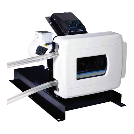
MASTERFLEX
®
B/T
®
Pump 77111-60
(US & Canada only) Toll Free 1-800-MASTERFLEX • 1-800-637-3739
(Outside US & Canada) 1-847-549-7600 • 1-847-381-7050
E-mail: techinfo@coleparmer.com
www.masterflex.com • www.coleparmer.com
®
OPERATING MANUAL:
®
B/T
RAPID-LOAD
PERISTALTIC PUMPS
AND DRIVES
System Model Nos.
77111-30
77111-37
77111-50
77111-55
77111-60
77111-67
77111-70
77111-71
77111-72
77111-77
77111-78
77111-79
77111-80
®
A-1299-1156
Edition 01
Advertisement
Table of Contents
Troubleshooting

Related Manuals for Cole Parmer Mastercraft B/T RAPID-LOAD 77111-30


Summary of Contents for Cole Parmer Mastercraft B/T RAPID-LOAD 77111-30
- Page 1 ® OPERATING MANUAL: ® ® RAPID-LOAD PERISTALTIC PUMPS AND DRIVES System Model Nos. 77111-30 77111-37 77111-50 MASTERFLEX ® ® Pump 77111-60 77111-55 77111-60 77111-67 77111-70 77111-71 77111-72 77111-77 77111-78 77111-79 77111-80 A-1299-1156 Edition 01 (US & Canada only) Toll Free 1-800-MASTERFLEX • 1-800-637-3739 (Outside US &...
- Page 2 Preface Preface © 2015 Cole-Parmer Instument Company LLC. All rights reserved. C-FLEX, NORPRENE, PHARMAPURE, PHARMED, TYGON – Reg TM Saint-Gobain Performance Plastics Corp. Trademarks bearing the ® symbol in this publication are registered in the U.S. and in other countries. PUMP FOR LIQUIDS ORIGINAL INSTRUCTIONS Cole-Parmer...
- Page 3 Preface Safety Precautions DANGER: High voltages exist and are accessible. Do not remove SAFETY cover of Drive or Controller. Use extreme caution when servicing PRECAUTIONS internal components. CAUTIONS: Risk of electric shock – this pump is supplied with a grounding conductor and grounding-type attachment plug. To reduce risk of electric shock, be certain that it is connected only to a properly grounded, grounding-type receptacle.
-
Page 5: Table Of Contents
Table of Contents Page Section 1 INTRODUCTION ........... .1-1 Application Data . - Page 7 Figures Figures Page RAPID-LOAD Pump and Drive Family .......1-3 RAPID-LOAD Pump and Drive ........1-4 Pump Mounting Dimensions .
- Page 9 Tables Tables Page Tubing Types ..........2-6 Cole-Parmer ®...
-
Page 11: Introduction
Introduction Section 1 This manual provides information for installing, operating and servicing ® ® ® the following models of MASTERFLEX RAPID-LOAD Peristaltic Pumps and Drives. MODEL TYPE 77111-72 Controller Only 115V AC for 77111-70 77111-71 Drive Only 115V AC for 77111-70 77111-79 Controller Only 230V AC for 77111-77 77111-78... -
Page 12: Application Data
Section 1 Introduction Application Data The gentle peristaltic action of these pumps is ideal for pumping highly viscous and shear-sensitive liquids. These pumps are also ideally suited for use where sterile conditions and purity are required. Toxic and hazardous fluids can be pumped with the proper selection of MASTERFLEX PerfectPosition B/T tubing since the fluid contacts only the tubing and not the pump. -
Page 13: General Description
Section 1 Introduction General Description The RAPID-LOAD® B/T peristaltic pump (see Figure 1) is mounted on a base and attached to a NEMA 56C frame motor or IEC-72 71-14F130 frame motor through a 5.45:1 gear head and adapter. Depending on the model, the motor is either supplied or customer furnished and is attached to the adapter by four bolts. -
Page 14: Rapid-Load Pump And Drive
Section 1 Introduction The maximum recommended rotor speed is 321 rpm. The pump rotor can turn either clockwise or counterclockwise. When turning clockwise (FWD) the top connection is for suction and the bottom connection is for discharge. The 321 rpm speed is obtained from the standard 1725 rpm fractional horsepower motor through the 5.45:1 gear reduction. -
Page 15: Installation And Setup
Installation and Setup Section 2 These units should be placed on a flat surface such as a floor, bench or table and should be near an electrical power source. Be sure to check data plate for proper voltage rating(s). PUMP MOUNTING 27.0 (685.80) (12.70) -
Page 16: Control Box Mounting Dimensions (Analog Models Only)
Section 2 Installation and Setup CONTROL BOX NOTE: The controller and bracket can be removed and located up to 10 feet away. MOUNTING Ø .220 DIMENSIONS 4 Places (Analog Models 77111-60 and 77111-67 Only) (184) (140) (130) (91) (140) Figure 2-3. Control Box Mounting Dimensions 77111-60 (115V). (240) (228) Ø... -
Page 17: Model 77111-80
Section 2 Installation and Setup Model 77111-80 This unit should be placed on a flat surface such as a floor, bench, or table and should be near a compressed air source. Unpack the drive and save packaging material until proper product operation has been verified. -
Page 18: Model 77111-50
Section 2 Installation and Setup MODEL 77111-50 Install customer-supplied motors in accordance with the following procedure. CAUTION: This product is intended for use with a motor that has a maximum speed of 1800 rpm, @ 1.0 HP (0.75 KW). Do not use a motor with a higher speed capacity. -
Page 19: Model 77111-55
Section 2 Installation and Setup MODEL 77111-55 Install customer-supplied motors in accordance with the following procedure. CAUTION: This product is intended for use with a motor that has a maximum speed of 1800 rpm, @ 1.0 HP (0.75 KW). Do not use a motor with a higher speed capacity. -
Page 20: Tubing Types
Section 2 Installation and Setup TUBING TYPES WARNING: Use only MASTERFLEX PerfectPosition B/T precision t ubing with MASTERFLEX pumps to ensure optimum performance . Use of other tubing may void applicable warranties. NOTE Use MASTERFLEX PerfectPosition B/T tubing. These pumps are designed to use PerfectPosition B/T tubing sizes 87 and 91 only. -
Page 21: Installing The Pump Tubing
Section 2 Installation and Setup INSTALLING THE WARNING: Power must be removed from pump before removing or installing tubing. Fingers or loose clothing could get caught in PUMP TUBING drive mechanism. Do not operate this pump without cover or (All Pump Models) interlock door properly closed and latched. -
Page 22: Tubing Retaining Pockets
Section 2 Installation and Setup PerfectPosition MARKS Figure 2-9. PerfectPosition Marks 4. If the new tube must be cut from a length of approved replacement tubing, a minimum of 32 inches will be required for a new tube. 5. Going with the natural lay or curvature of the tubing, wrap the tubing around the assembly and insert the tubing in the lower retaining pocket. -
Page 23: Operation
Operation Section 3 Control Display Functions Models 77111-70 77111-72 77111-77 77111-79 Figure 3-1. Control Panel A) DOWN ARROW (DECREMENT)—Decrease value of a flashing display. B) UP ARROW (INCREMENT)—Increase value of a flashing display. C) DISP—Set dispense volume, copy amount, or dispense time. D) FLOW—Set flow rate for selected tubing size. - Page 24 Section 3 Section 3 Operation Operation A) EXTERNAL RECEPTACLE B) MOTOR RECEPTACLE C) LINE CORD D) INTERLOCK CONNECTOR E) T12A FUSE (115V AC); T6A FUSE (230V AC) F) POWER SWITCH — ALL SETTINGS ARE RETAINED IN MEMORY Figure 3-2. Connectors and Switch on Controller Side Panel 1.
- Page 25 Section 3 Operation Calibration 1. Select correct tubing size and flow rate. 2. Press CAL, calibration volume appears. 3. Press STOP/START, the pump will use its stored memory to dispense the specified calibration sample quantity. The pump will stop automatically. 4.
- Page 26 Section 3 Operation DISPense/copy A first press of the DISP key results in the last entered dispense volume being displayed. The “VOL” annunciator will illuminate and flash. The INC/DEC keys are used to change the dispense volume, if desired. The STOP/START key then initiates delivery of the set volume.
- Page 27 Section 3 Operation Remote Control Setup 1. Place the power switch in the off position. CAUTION: Power must be turned off before connecting the external remote control cable to prevent damage to the drive. 2. Connect the cable from the external remote control to the mating receptacle on the bottom panel.
- Page 28 Section 3 Operation Remote Control Setup NOTE: The maximum flow rate for a tubing will change after a calibration is performed. To retain control of the entire flow range, the “HI” scale (continued) setting must be changed to the new maximum flow rate after a calibration is performed.
- Page 29 Section 3 Operation Remote Control Setup A1) RED/YELLOW B1) BLUE (continued) C1) GREEN D1) YELLOW E1) WHITE F1) ORANGE G1) BLACK H1) BROWN I1) VIOLET J1) RED K1) GREY L1) TAN M1) PINK N1) RED/GREEN O1) RED/BLACK P1, Q1, R1) N.C. A) STOP/START B) CW/CCW C) OUTPUT 0-20mA;...
-
Page 30: Models 77111-60 And 77111-67
Section 3 Operation Models 77111-60 Models 77111-60 (115V model) and 77111-67 (230 V model) are supplied with an electronic controller (see Figure 3-5) for controlling and 77111-67 pump speed. Controller 1. Place FWD-OFF-REV switch in the desired position, clockwise (FWD) or counterclockwise (REV) direction. 2. -
Page 31: Model 77111-80
Section 3 Operation Model 77111-80 Adjust flow rate with adjustment knob on top of regulator. Vary flow rate from 10 psig to 60 psig. At higher pressures, the pump speed may exceed 321 rpm. CAUTION: Do not exceed 321 rpm. Speeds in excess of 321 rpm may cause damage to unit. -
Page 32: Models 77111-30 And 77111-37
Section 3 Operation The following chart highlights items included in each model and the Models 77111-30 operating controls. and 77111-37 Operating Controls Model No. Motor Included ON-OFF Switch 77111-30 77111-37 Figure 3-7. Model 77111-30 3-10 ® RAPID-LOAD ® Peristaltic Pumps and Drive Operating Manual Cole-Parmer... -
Page 33: Maintenance And Troubleshooting
Maintenance and Troubleshooting Section 4 REPLACING Tools Required: Phillips screwdriver MOTOR BRUSHES WARNING: Power must be removed from motor before performing this procedure. MODELS 77111-60 1. Cut off power to the pump by disconnecting line cord or, if wired 77111-67 permanently, by removing the fuse. -
Page 34: Replacing Rollers
Section 4 Maintenance and Troubleshooting REPLACING ROLLERS To replace rollers: 1. Using a retaining ring tool (Part Number 109852-CR), remove the retaining rings from the ends of the roller axles and slide the rollers off. Take care to avoid opening the retaining rings too wide. 2. -
Page 35: Motor Replacment
Section 4 Maintenance and Troubleshooting MOTOR Tools required: REPLACEMENT 56 C frame mounting, 5/16 inch Hex key. ISO-71 frame mounting, 10 mm wrench. To install replacement motor refer to Figure 4-3 and follow these steps: 1. Apply anti-seize compound to shaft and key. Slide motor forward to engage the male motor coupling with the female gear head coupling. -
Page 36: Replacement Parts
Section 4 Maintenance and Troubleshooting Replacement Parts The following list identifies the replaceable parts and includes the part numbers. Description Part Number per Unit Motor Brush Set (115V AC), Model 77111-60 A-4156-CR Motor Brush Set (115V AC), Models 77111-70 and 77111-71 113054-CR Motor Brush Set (230V AC), Model 77111-67 A-4158-CR... -
Page 37: Troubleshooting Models 77111-70 And 77111-77
Section 4 Maintenance and Troubleshooting Troubleshooting Symptom Cause Remedy A. Motor does not rotate. A1. No power. 1. Check fuse and replace if defective. Models 77111-70 Display does not light. 2. Check that unit is plugged into a live line. and 77111-77 3. - Page 39 Specifications Section 5 Models 77111-70 Output: Speed: 11 to 321 rpm 77111-71 Torque output, Maximum: 1940 oz-in (140 kg • 77111-72 Speed regulation: 77111-77 Line ±0.25% F.S. Load ±0.25% F.S. 77111-78 Drift ±0.25% F.S. 77111-79 Display: Four-digit, seven segment LED Remote outputs: Voltage speed output (0–10V DC)
- Page 40 Section 5 Specifications Models 77111-70 Environment: Temperature, Operating: 32° to 104°F (0° to 40°C) 77111-71 Temperature, Storage: –49° to 149°F (–45° to 65°C) 77111-72 Humidity (non-condensing): 10% to 90% 77111-77 Altitude: Less than 2000 m Pollution Degree: Pollution Degree 3 (Sheltered locations) 77111-78 Noise Level: <75 dBA @ 1 meter...
- Page 41 Section 5 Specifications Models 77111-60 Output: Pump Speed: 12 to 321 rpm and 77111-67 Torque output, maximum: 1100 oz-in (104 kg • Tubing compatibility: Sizes B/T 87 or B/T 91 Flow Range: Up to 11.1 GPM (42.0 LPM) Input: Supply voltage limits: Model 77111-60 90 to 130 Vrms @ 60 Hz Model 77111-67...
-
Page 42: Model 77111-80
Section 5 Specifications Model 77111-80 Output: Pump Speed: 35 to 321 rpm Torque output, maximum: 2200 oz-in (208 kg-cm) Tubing compatibility: Sizes B/T 87 and B/T 91 Flow Range: up to 11.1 GPM (42.0 LPM) Input: Compressed air: 30 cfm (0.85 m /min) @ 60 psig Construction: Dimensions (L ×... - Page 43 Section 5 Specifications Models 77111-30 Output: Pump Speed: and 77111-37 Model 77111-30 321 rpm Model 77111-37 271 rpm Torque output, maximum: 2200 oz-in (208 kg-cm) Tubing compatibility: Sizes B/T 87 or B/T 91 Flow Range: Up to 11.1 GPM (42.0 LPM) Input: Supply voltage limits: Model 77111-30...
-
Page 44: Models 77111-50 And 77111-55
Section 5 Specifications Models 77111-50 Output: Pump Speed: 35 to 321 rpm and 77111-55 Torque output, maximum: 2200 oz-in (208 kg-cm) Tubing compatibility: Sizes B/T 87 or B/T 91 Flow Range: Up to 11.1 GPM (42.0 LPM) Input: 1750 rpm maximum 1 hp (0.75 kW) 586 oz-in minimum NEMA 56C motor for 77111-50 or... -
Page 45: Warranty
Warranty, Product Return and Section 6 Technical Assistance Warranty Use only MASTERFLEX precision tubing with MASTERFLEX pumps to ensure optimum performance. Use of other tubing may void applicable warranties. This product is warranted against defects in material or workmanship, and at the option of the manufacturer or distributor, any defective product will be repaired or replaced at no charge, or the purchase price will be refunded to the purchaser, provided that: (a) the warranty claim is made in writing... - Page 46 Section 6 Warranty Product Return To limit charges and delays, contact the seller or Manufacturer for authorization and shipping instructions before returning the product, either within or outside of the warranty period. When returning the product, please state the reason for the return. For your protection, pack the product carefully and insure it against possible damage or loss.
- Page 48 ® (US & Canada only) Toll Free 1-800-MASTERFLEX • 1-800-637-3739 (Outside US & Canada) 1-847-549-7600 • 1-847-381-7050 www.masterflex.com • www.coleparmer.com E-mail: techinfo@coleparmer.com *EN809 manufactured by: Cole-Parmer Instrument Company LLC 28W092 Commercial Avenue Barrington, IL 60010 Printed in U.S.A. Printed in U.S.A.
Need help?
Do you have a question about the Mastercraft B/T RAPID-LOAD 77111-30 and is the answer not in the manual?
Questions and answers