Table of Contents
Advertisement
Quick Links
Model 77720-00
(US & Canada only) Toll Free 1-800-MASTERFLEX • 1-800-637-3739
(Outside US & Canada) 1-847-549-7600 • 1-847-381-7050
E-mail: techinfo@coleparmer.com
www.masterflex.com • www.coleparmer.com
OPERATING MANUAL:
FH10
Pump System
Model Nos.
77720-00
77720-02
77720-04
®
A-1299-7290
Edition 01
Advertisement
Table of Contents

Related Manuals for Cole Parmer Masterflex Catalyst FH10 Microflex


Summary of Contents for Cole Parmer Masterflex Catalyst FH10 Microflex
- Page 1 OPERATING MANUAL: FH10 ® Pump System Model Nos. 77720-00 77720-02 77720-04 Model 77720-00 A-1299-7290 Edition 01 (US & Canada only) Toll Free 1-800-MASTERFLEX • 1-800-637-3739 (Outside US & Canada) 1-847-549-7600 • 1-847-381-7050 E-mail: techinfo@coleparmer.com www.masterflex.com • www.coleparmer.com...
- Page 2 Preface Preface © 2014 Cole-Parmer Instrument Company LLC. All rights reserved. NORYL – Reg TM General Electric Company C-FLEX, PHARMED, TYGON – Reg TM Saint-Gobain Performance Plastics Corp. VITON – Reg TM E.I. duPont DeNemours & Co. These products are covered by one or more of the following U.S. and corresponding foreign patents: D605,286S. Trademarks bearing the symbol in this publication are registered in the U.S.
- Page 3 Preface Safety Precautions SAFETY DANGER: Remove power from the Pump System before any cleaning operation is started. PRECAUTIONS WARNINGS: Tubing breakage may result in fluid being sprayed from pump. Use appropriate measures to protect operator and equipment. Before installing tubing into the Pump Head remove power or shut off the drive.
-
Page 5: Table Of Contents
Table of Contents Table of Contents Page Section 1 INTRODUCTION ..........1-1 General Description . - Page 7 Figures Figures Page FH10 MICROFLEX Pump System ........1-1 Pump –...
-
Page 9: Introduction
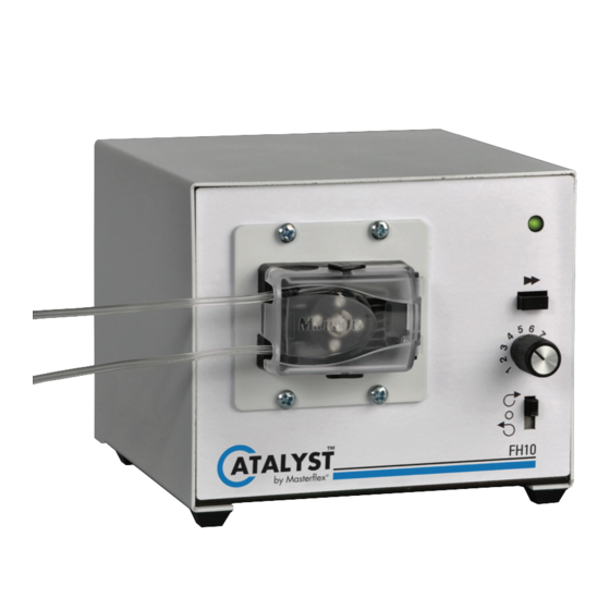
Introduction Section 1 The FH10 MICROFLEX Pump System is designed to pump fluid through Microbore tubing by means of peristaltic action at very low flow rates. It is ideal for sanitizers, reagent dispensing, analyzers, printing systems, controlled feeding and non-human infusion procedures. GENERAL The FH10 MICROFLEX Pump System accommodates one tube at controlled speeds as low as 1.7 rpm. - Page 10 Section 1 Introduction GENERAL The single-turn, adjustable Speed Control, Figure 1-2, provides variable flow-operation. The green PWR On indicator lights whenever the pump DESCRIPTION is operating. The Power On/Direction Switch turns power on when (continued) either clockwise or counterclockwise pump rotor direction is selected. The ▶...
-
Page 11: Installation And Setup
Installation and Setup Section 2 Setup Use only Microbore Autoanalysis tubing with MICROFLEX pumps to ensure optimum performance. Use of other tubing may void applicable warranties. Selecting Tubing Size Appendix A provides a list of tubing sizes which will work efficiently with the FH10 MICROFLEX Pump System. -
Page 12: Installing Tubing In Pump Head
Section 2 Installation and Setup Installing Tubing WARNING: Before installing tubing into the Pump Head remove power or shut off the drive. Fingers or loose clothing could be in Pump Head caught in the rollers. 1. Place the Power On/Direction Switch, Figure 1-2, in the center (Off) position. -
Page 13: Connecting Primary Power
Section 2 Installation and Setup Installing Tubing 5. As you close the door you will notice the occlusion bed moves toward the rotor and contacts the tubing. Once the door is closed and it in Pump Head appears to have any excess tubing, open the door and remove excess by (continued) opening one of the retainers and gently pulling on the tube. -
Page 14: Remote Start/Stop Connection
Section 2 Installation and Setup Remote Start/Stop Terminals 3 and 4 on the rear panel terminal strip, Figure 1-3, are used for remote start/stop operation. Pump direction and speed are not remotely Connection controllable. In non-remote operation, these terminals are connected together by a Shorting Bar. -
Page 15: Operation
Operation Section 3 This section describes the procedures for obtaining desired performance. Flow rate is determined by the drive speed and the tubing size. WARNING: Tubing breakage may result in fluid being sprayed from pump. Use appropriate measures to protect operator and equipment. -
Page 17: Maintenance
Maintenance Section 4 Cleaning DANGER: Remove power from the Pump System before any cleaning operation is started. Clean exterior surfaces of case, control panel and pump rollers using a dry or damp cloth. Never immerse nor use excessive fluid. Cole-Parmer FH10 MICROFLEX ®... -
Page 19: Replacement Parts And Accessories
Replacement Parts and Accessories Section 5 Replacement Parts Description Part No. Knob 110199 Shorting Bar A-4402 Pump Head Assembly - 3 Roller 111004-CR Pump Head Assembly - 4 Roller 111005-CR Accessories Description Part No. Universal Power Supply 100-240V AC 77200-07 Line Cord, Australia 50001-60 Line Cord, Denmark... -
Page 21: Specifications
Specifications Section 6 Output: Operating Speed: Models 77720-00 1.7 to 10 rpm 77720-02 13 to 80 rpm 77720-04 50 to 300 rpm Maximum No. of Tubes: Direction of rotation: Clockwise and Counterclockwise Input: Supply Voltage/Frequency: Model: 77720-00, 77720-02 115V AC nominal, 50/60 Hz and 77720-04 (90–130V AC) @ 400 mA AC 230 V AC nominal, 50/60 Hz... - Page 22 Section 6 Specifications Construction: Dimensions (L × W × H): 6.75 in × 5.25 in × 4.5 in (17.2 cm × 13.4 cm × 11.4 cm) Weight: 3.3 pounds (1.5kg) Color: Light Gray (5% black) Material: Pump Head: PPS, polyester, stainless steel Case: Painted Steel Enclosure Rating:...
-
Page 23: Warranty, Product Return And Technical Assistance
Warranty, Product Return and Section 7 Technical Assistance Warranty Use only Microbore Autoanalysis tubing with MICROFLEX pumps to ensure optimum performance. Use of other tubing may void applicable warranties. This product is warranted against defects in material or workmanship, and at the option of the manufacturer or distributor, any defective product will be repaired or replaced at no charge, or the purchase price will be refunded to the purchaser, provided that: (a) the warranty claim is made in writing... -
Page 24: Product Return
Section 7 Warranty, Product Return and Technical Assistance Product Return To limit charges and delays, contact the seller or Manufacturer for authorization and shipping instructions before returning the product, either within or outside of the warranty period. When returning the product, please state the reason for the return. -
Page 25: Available Microbore Autoanalysis Tubing
Appendix A Section 8 CAUTION: Tubing for use with the MICROFLEX Pump Systems is Microbore Autoanalysis Tubing. Use of tubing other than that specified will result in poor pumping performance and/or pump system damage and voiding of applicable warranty. Available Microbore Autoanalysis Tubing PHARMED ®... -
Page 26: Tubing Flow Rates
Section 8 Appendix A Tubing Flow Rates See the following table for Tubing size versus ID and flow rates. Flow rates are for water pumped at room temperature and 0 psi. Flow rate is determined by drive, speed, tubing size and material. Tubing Tubing Flow Rate... - Page 28 (US & Canada only) Toll Free 1-800-MASTERFLEX • 1-800-637-3739 (Outside US & Canada) 1-847-549-7600 • 1-847-381-7050 www.masterflex.com • www.coleparmer.com E-mail: techinfo@coleparmer.com *EN809 manufactured by: Cole-Parmer Instrument Company LLC 28W092 Commercial Avenue Barrington, IL 60010 Printed in U.S.A.
Need help?
Do you have a question about the Masterflex Catalyst FH10 Microflex and is the answer not in the manual?
Questions and answers