
Subscribe to Our Youtube Channel
Related Manuals for Riken Keiki SP-230 Series


Summary of Contents for Riken Keiki SP-230 Series
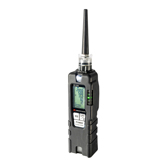
- Page 1 PT0E-2241 Portable Gas Leak Checker SP-230 Series SP-230 (Type F) SP-230 (Type H2) Operating Manual (PT0-213)
-
Page 2: Table Of Contents
Contents 1. Product Overview ............................2 1-1. Introduction ............................2 1-2. Intended use ............................2 1-3. DANGER, WARNING, CAUTION, and NOTE ..................3 1-4. Checking standards and explosion-proof specifications ............... 3 2. Important Safety Information ........................4 2-1. Danger information ..........................4 2-2. -
Page 3: Product Overview
Regardless of the warranty period, RIKEN KEIKI does not accept any liability for accidents or damage resulting from use of the product. Be sure to read the warranty policy set forth on the warranty. -
Page 4: Danger, Warning, Caution, And Note
1. Product Overview 1-3. DANGER, WARNING, CAUTION, and NOTE This manual uses the following headings to ensure safe and effective work: This indicates situations in which improper handling may result in DANGER fatal or serious injury to persons or serious damage to property. This indicates situations in which improper handling may result in WARNING serious injury to persons or serious damage to property. -
Page 5: Important Safety Information
2. Important Safety Information Important Safety Information To maintain the performance of the product and to ensure safe use, always observe the following DANGER, WARNING, and CAUTION instructions. 2-1. Danger information DANGER Explosion-proofing Do not modify or alter the circuitry or configuration. When using the product in hazardous areas, the following precautions must be observed to safeguard against static electricity hazards: ①... -
Page 6: Warning Information
2. Important Safety Information 2-2. Warning information WARNING If an abnormality occurs If an abnormality is discovered in the product, contact RIKEN KEIKI immediately. Visit our website for information on the nearest RIKEN KEIKI office. Website: https://www.rikenkeiki.co.jp/ Sampling point pressure ... -
Page 7: Caution Information
2. Important Safety Information 2-3. Caution information CAUTION Do not use the product in locations where it may be exposed to oil or chemicals, etc. ‧ Avoid using the product in locations where the product may be splashed with liquids such as oil and chemicals. - Page 8 If you do not intend to use the product for extended periods, store with the batteries removed. Battery leaks may result in fire or injury. After a period of extended storage, be sure to perform fresh air adjustment before resuming use. For information on readjustment including fresh air adjustment, contact RIKEN KEIKI. 7/49...
-
Page 9: Important Notes Related To Explosion Resistance
B: Month of manufacture (1 to 9 for January to September, X for October, Y for November, Z for December) C: Manufacturing lot D: Serial number E: Factory code Manufacturer RIKEN KEIKI Co., Ltd. 2-7-6 Azusawa, Itabashi-ku, Tokyo, 174-8744, Japan Website: https://www.rikenkeiki.co.jp/ 8/49... -
Page 10: Product Configuration
3-1. Main unit and accessories Open the box and packaging and inspect the product and accessories. If anything is missing, contact RIKEN KEIKI. Main unit For detailed information on the names and functions of product parts and the LCD display, refer to ‘3-2. - Page 11 3. Product Configuration Accessories Protective ×1 Alkaline ×2 cover (fitted) batteries Tapered ×1 Hand strap ×1 nozzle Operating ×1 - Manual Replacement 1 bag Product waterproof - ×1 (set of 5) warranty filters Optional accessories Filter (set of 5) Filter to prevent foreign matter Tertiary filter ingress when replacing the Low-density...
- Page 12 3. Product Configuration Note: ・ Gas leak checkers in the vicinity may also come into contact with Inspection gas the gas. ・ Do not perform in a confined space. Tube EPDM ⌀6 × ⌀3.5 × 500 mm Attachment used for inserting annealed copper pipe into water heaters or other hot equipment.
-
Page 13: Part Names And Functions
3. Product Configuration 3-2. Part names and functions This section describes the names and functions of the various parts of the main unit and the LCD display. Main unit ⑦ ② ⑧ ③ ① ④ ⑤ ⑥ ② ⑨ Name Function LCD display Displays gas concentration, gas name, alarms, and other information. - Page 14 3. Product Configuration LCD display Name Function Operating status icon Indicates the operating status in detection mode. (When normal: ① Blinks.) Flow confirmation icon Indicates suction status. (When normal: Rotates.) ② Gas concentration display Displays the gas concentration and units. ③...
-
Page 15: Alarm Functions
Example display for low flow rate LCD display If a fault alarm occurs, determine the cause and take appropriate action. If the problem lies with the product and the fault occurs repeatedly, contact RIKEN KEIKI immediately. NOTE The low flow rate ([FAIL LOW FLOW]), adjustment abnormality ([FAIL AIR CAL]), and clock abnormality ([FAIL CLOCK]) alarms can be canceled by pressing the PUMP RESET/Light button. -
Page 16: Usage Instructions
5. Usage Instructions Usage Instructions 5-1. Usage note The operating precautions apply to both users who have previously used the product and first-time users. Failure to comply with these precautions may result in failure of the product or inability to detect gas correctly. - Page 17 5. Usage Instructions CAUTION Be sure to turn off the power for the product before replacing the batteries. Replace the batteries in a safe place. When replacing the batteries, replace both batteries with new ones at the same time. ...
-
Page 18: Startup Procedure
5. Usage Instructions 5-4. Startup procedure When the power is turned on, self diagnosis is performed, and then the product enters detection mode. NOTE Turning on the power causes the LCD and all of the lamps to operate. (The buzzer also operates if the operation tone is turned on.) Before operating the product, check that these operations function correctly. - Page 19 5. Usage Instructions NOTE When the clock function is enabled, a clock abnormality ([FAIL CLOCK]) will occur if the batteries are removed for at least five minutes—for example, during battery replacement—or if the power is turned on after inserting the batteries with the incorrect polarity. Cancel this by pressing the PUMP RESET/Light button to display the date and time setting screen.
-
Page 20: Basic Operation Flow
5. Usage Instructions 5-5. Basic operation flow The product is used in detection mode after turning on the power. (Display examples: Hydrogen model) PUMP RESET/Light button Buzzer button Hold down for Hold down for 3 seconds 3 seconds <Operation tone and <Function button>... -
Page 21: Gas Detection
5. Usage Instructions 5-6. Gas detection In detection mode, hold the tip of the tapered nozzle close to the location in question to detect the gas. Gas is drawn in. The detected gas concentration is displayed as a bar meter on the LCD display and LED display unit. -
Page 22: Selecting Alarm Setpoints
5. Usage Instructions 5-7. Selecting alarm setpoints As shipped, the product is set to detect R600a (Type F) or H2 (Type H2), with the alarm setpoint set to 30. The alarm setpoint can be selected to one of five levels to suit the environment in which the gas to be detected is present. -
Page 23: Fresh Air Adjustment
5. Usage Instructions 5-8. Fresh air adjustment Perform fresh air adjustment under ambient measurement conditions after detecting a high-concentration gas or following an alarm triggered by changes in temperature or humidity. * Confirm that the surrounding air is fresh when performing fresh air adjustment. (Display examples: Hydrogen model) Hold down the Buzzer button and... -
Page 24: Snap Logger
5. Usage Instructions 5-9. Snap logger Peak values can be recorded during measurement. Up to 256 data items can be recorded, and when the maximum number of items is reached, the oldest data is overwritten by new data. This function is enabled when the clock function is enabled. By default, the clock function is disabled. Turn on the clock function before using the snap logger function. -
Page 25: Peak Hold Function
5. Usage Instructions 5-10. Peak hold function If the peak hold function is enabled, the most recent peak value will be constantly displayed on the bar meter display. (Display examples: Hydrogen model) Hold down the PUMP RESET/Light button (for at least three seconds) in detection mode. -
Page 26: Toggling The Operation Tone And Alarm Sound On And Off
5. Usage Instructions 5-11. Toggling the operation tone and alarm sound on and off The operation tone and alarm sound can be toggled on and off. (Display examples: Hydrogen model) 1 Press the Buzzer button in detection mode. Pressing the Buzzer button cycles through the operation tone and alarm sound settings. Operation tone on Operation tone on Operation tone off... -
Page 27: Turning On The Light
5. Usage Instructions 5-12. Turning on the light The light can be turned on when using the product in dark locations. Press the PUMP RESET/Light button. The light turns on. The light will go out automatically approximately two minutes after it is turned To turn off the light, press the PUMP RESET/Light button again. -
Page 28: Display Mode Setting Procedure
6. Display Mode Setting Procedure Display Mode Setting Procedure 6-1. Selecting display mode Display mode lets users review and change various display settings and perform other operations. (Display examples: Hydrogen model) Hold down the PUMP RESET/Light button (for at least three seconds) in detection mode. - Page 29 6. Display Mode Setting Procedure Display mode overview Item LCD display Details Peak display Displays the maximum concentration detected since the power was turned on. * To clear the peak value, hold down the Buzzer button (for at least three seconds) until [PEAK CLR] is displayed.
-
Page 30: Target Gas Selection Setting
6. Display Mode Setting Procedure 6-2. Target gas selection setting The default setting for the product is normally [R600a] for Type F and [H2] for Type H2, but gas concentration can be detected simply by switching to another pre-registered gas. If assigned to the function button, it can also be set by holding down the Buzzer button (for at least three seconds) while in detection mode. - Page 31 6. Display Mode Setting Procedure Gas list for freon gas (Type F) Unit Scale Scale Scale Scale Scale Gas name conversion Display (standard name) (guide) (ppm) (ppm) (ppm) (ppm) (ppm) (g/year) R600a (Isobutane) R600A 2000 Approx. 2.7 R290 (Propane) R290 2000 Approx.
- Page 32 6. Display Mode Setting Procedure Gas list for hydrogen gas (Type H2) Scale 1 Scale 2 Scale 3 Scale 4 Scale 5 Gas name (standard name) Display (ppm) (ppm) (ppm) (ppm) (ppm) Methane (calibration gas) 2000 Hydrogen (calibration gas) 2000 Acetylene C2H2 2000...
-
Page 33: Log Data Display
6. Display Mode Setting Procedure 6-3. Log data display Data recorded by the snap logger can be viewed. The REC DATA screen is displayed only when the clock function is enabled. (Refer to ‘7-3. Clock function ON/OFF setting’ (p. 36).) (Display examples: Hydrogen model) Display mode Press the... -
Page 34: User Mode Setting Procedure
7. User Mode Setting Procedure User Mode Setting Procedure 7-1. Selecting user mode This can be used for maintenance such as adjusting the internal clock. (Display examples: Hydrogen model) Press the button several times in display mode to display [USER], then press the POWER/ALARM POINT button. - Page 35 7. User Mode Setting Procedure User mode overview Item Details LCD display Date and time setting This sets the date and time for the internal clock. (Refer to ‘7-2. Date and time setting’ (p. 35).) * Displayed only when the clock function is enabled.
-
Page 36: Date And Time Setting
7. User Mode Setting Procedure 7-2. Date and time setting This sets the date and time for the internal clock. The date and time setting screen is displayed only when the clock function is enabled. Turn on the clock function as described in ‘7-3. Clock function ON/OFF setting’ (p. 36) before setting the date and time. Press the POWER/ALARM POINT button on the user mode DATE screen. -
Page 37: Clock Function On/Off Setting
7. User Mode Setting Procedure 7-3. Clock function ON/OFF setting Sets the clock function on and off. By default, the clock function is disabled. Turn on the clock function in order to display the date and time at startup or to use the snap logger function. Press the POWER/ALARM POINT button on the user mode CLOCK screen. -
Page 38: Function Button Setting
7. User Mode Setting Procedure 7-4. Function button setting The function button can be set. A function can be assigned and called up by holding down the Buzzer button (for at least three seconds) while in detection mode. By default, the target gas selection setting is assigned. Press the POWER/ALARM POINT button on the user mode KEY SET screen. - Page 39 7. User Mode Setting Procedure List of functions that can be assigned to the function button Functions LCD display Details Assigns the target gas selection setting to Target gas selection setting the function button. (Refer to ‘6-2. Target gas selection setting’ (p.
-
Page 40: Maintenance
8. Maintenance Maintenance The product is a precision device. Maintain and inspect the product at regular intervals to ensure product performance and improve gas leak detection reliability. 8-1. Maintenance intervals and maintenance items Maintain the following items at regular intervals before use: ・... - Page 41 8. Maintenance Maintenance service RIKEN KEIKI provides services related to regular maintenance, including span adjustment, as well as other adjustments and maintenance. Preparing a calibration gas requires dedicated equipment, including gas cylinders of the specified concentration and gas sampling bags.
-
Page 42: Cleaning Instructions
8. Maintenance 8-2. Cleaning instructions Clean the product if it becomes excessively dirty. Be sure to turn off the power before cleaning, and wipe clean using a cloth. Do not clean using water or organic solvents for cleaning, as these may cause the product to malfunction. - Page 43 8. Maintenance Replace the Teflon filter contained inside the seal with a new filter. Filter Seal Reattach the seal with the Teflon filter inside to the cap. Check to confirm that the rib securely engages with the groove here. Groove Reattach the cap with seal fitted to the main unit.
- Page 44 If the sensors cannot be adjusted using span adjustment, the readings are not restored after fresh air adjustment, or the readings fluctuate, the sensors are at the end of their life. Contact RIKEN KEIKI for replacement. Battery replacement For information on how to replace the batteries, refer to ‘5-3. Battery replacement’ (p. 15).
-
Page 45: Storage And Disposal
9-2. Procedures for use after storage CAUTION Be sure to perform gas adjustment if the product is used again after a period in storage. Contact RIKEN KEIKI to request readjustment and gas adjustment. 44/49... -
Page 46: Product Disposal
9. Storage and Disposal 9-3. Product disposal Dispose of the product as industrial waste (incombustible) in accordance with local regulations. WARNING Dispose of the batteries in accordance with procedures specified by the local authority. <Disposal in EU member states> When disposing of the product in an EU member state, dispose of the batteries separately. -
Page 47: Troubleshooting
If the error persists The sensor is defective. [FAIL SENSOR] even after turning the power back on again several times, contact RIKEN KEIKI to request sensor replacement. Low battery voltage Turn off the power and replace with new alarm indication The battery level is low. - Page 48 Turn the power off and on several times. The power was turned on The pump may start working. If the at a cold temperature or problem persists, contact RIKEN KEIKI to after an extended period. request pump replacement. Contact RIKEN KEIKI to request pump The pump is deteriorated.
-
Page 49: Product Specifications
11. Product Specifications Product Specifications SP-230 (Type F) SP-230 (Type H2) Model For freon detection For hydrogen detection Detection principle Hot-wire semiconductor type Detection target Refer to ‘Gas list for hydrogen gas’ Refer to ‘Gas list for freon gas’ (p. 30) (p. -
Page 50: Appendix
12. Appendix Appendix 12-1. Terminology vol% Indicates gas concentrations in units of parts per hundred by volume. Indicates gas concentration in units of parts per million by volume. Abbreviation for “lower explosive limit”. The lower explosive limit is the minimum concentration of a combustible gas mixed in air at which ignition will result in explosion. - Page 51 Revision history Issue Revision details Issue date First issue (PT0-2240) April 19, 2024 CE Declaration of conformity June 12, 2024...
Need help?
Do you have a question about the SP-230 Series and is the answer not in the manual?
Questions and answers