
Related Manuals for Riken Keiki 04 Series


Summary of Contents for Riken Keiki 04 Series
- Page 1 PT0E-1892 Portable Gas Monitor 04 Series Operation Manual (PT0-189) 2-7-6 Azusawa, Itabashi-ku, Tokyo, 174-8744, Japan Website: https://www.rikenkeiki.co.jp/...
-
Page 2: Table Of Contents
Contents Contents 1. Product Overview .................................4 1-1. Introduction ................................4 1-2. Intended use .................................6 1-3. DANGER, WARNING, CAUTION, and NOTE .....................7 1-4. Checking standards and explosion-proof specifications ..................8 2. Important Safety Information ............................9 2-1. Danger information ...............................9 2-2. Warning information ............................12 2-3. - Page 3 Contents 5-5. Measuring gas concentration ..........................51 5-6. Checking the gas concentration, alarm setpoints, etc. (display mode) ............. 53 5-6-1. Procedure for displaying display mode ....................53 5-6-2. Items displayed in display mode ......................54 5-7. Turning off the power ............................59 6.
-
Page 4: Product Overview
The contents of this manual are subject to change without notice to allow product improvements. Any duplication or reproduction of this manual without permission is prohibited, whether in whole or in part. Riken Keiki accepts no liability for accidents or damage resulting from use of the product, whether within or outside the warranty period. - Page 5 1. Product Overview 1-1. Introduction Models covered by this operation manual OX-04G OX-04 CO-04 HS-04 CO-04 (C-) CX-04 SC-04 (SO2, NO2, HCN) <This manual> operation In this operation manual, where descriptions differ according to the model, the following icons are used to indicate each of the models: OX G OX-04G...
-
Page 6: Intended Use
1. Product Overview 1-2. Intended use 1-2. Intended use The product is a portable gas monitor for personal use designed to detect gases in the surrounding atmosphere. It measures concentrations of toxic gases and oxygen in the atmosphere and issues an alarm when gas concentrations reach preset levels, thereby alerting users to the hazards of gas poisoning and oxygen deficiency. -
Page 7: Danger, Warning, Caution, And Note
1. Product Overview 1-3. DANGER, WARNING, CAUTION, and NOTE 1-3. DANGER, WARNING, CAUTION, and NOTE This operation manual uses the following categories to indicate potential damage/hazards if the user disregards the information provided and uses the product incorrectly: This indicates situations in which improper handling may result in DANGER fatal or serious injury or significant property damage. -
Page 8: Checking Standards And Explosion-Proof Specifications
1. Product Overview 1-4. Checking standards and explosion-proof specifications 1-4. Checking standards and explosion-proof specifications The product specifications will vary depending on the specific standards and explosion-proof certification. Check the actual product specifications before use. For CE marking models, refer to the Declaration of Conformity at the end of this document. -
Page 9: Important Safety Information
2. Important Safety Information 2-1. Danger information Important Safety Information To maintain the performance of the product and to ensure safe use, always observe the following DANGER, WARNING, and CAUTION instructions. 2-1. Danger information DANGER Explosion-proofing Do not modify or alter the circuitry or configuration. ... - Page 10 2. Important Safety Information 2-1. Danger information The battery specifications are as follows: <Dry cell specifications> ・ The explosion-proof class is Ex ia IIC T4 Ga. ・ The ratings are as follows: ・ Japan models: Power source: 3 V DC (Toshiba LR03 battery × 2) Ambient temperature: −40 °C to +60 °C ・...
- Page 11 2. Important Safety Information 2-1. Danger information ・ Export models: Power source: 3 V DC, 1 mA (Toshiba LR03, Duracell MN2400, or Duracell PC2400 battery × 2) <Rechargeable battery specifications> eneloop (BK-4MCC) (Panasonic) rechargeable battery × 2 Guidelines <Export models (IECEx)> <Export models (ATEX)>...
-
Page 12: Warning Information
2. Important Safety Information 2-2. Warning information 2-2. Warning information WARNING Air calibration in the atmosphere When air calibration is performed in the atmosphere, check the atmosphere for freshness before starting. The presence of interference gases will prevent proper air calibration. The presence of interference gases is also extremely dangerous because the product may not detect actual gas leaks correctly. - Page 13 2. Important Safety Information 2-2. Warning information For calibration, use a standard gas consisting of the detection target gas diluted with nitrogen or air. Calibration can be performed with a gas mixture that includes other components; however, such calibrations will result in poor sensitivity and inaccurate concentration readings.
- Page 14 2. Important Safety Information 2-2. Warning information WARNING Handling the calibration gas The carbon monoxide sensor with hydrogen compensation must be calibrated separately for carbon monoxide and hydrogen. If hydrogen sensitivity calibration is not performed, carbon monoxide readings may be inaccurate due to hydrogen interference.
-
Page 15: Caution Information
2. Important Safety Information 2-3. Caution information 2-3. Caution information CAUTION Do not use the product in locations where it may be exposed to oil, chemicals, or other such substances. Avoid deliberately submerging the product in water. Do not use the product in locations where it may be exposed to oil, chemicals, liquids, or other such substances. Do not use walkie-talkies near the product. - Page 16 2. Important Safety Information 2-3. Caution information SC-04 (HCN): <Continuous use environment> Temperature: −20 °C to +50 °C Humidity: 10 %RH to 90 %RH <Temporary use environment> Temperature: −20 °C to +60 °C Humidity: 0 %RH to 95 %RH Avoid using for extended periods in locations exposed to direct sunlight.
- Page 17 2. Important Safety Information 2-3. Caution information Always replace the batteries with new batteries. Note the polarity when inserting the batteries. If inserted with the wrong polarity, the screen for setting date and time will appear the next time the power is turned on. ...
- Page 18 If [FAIL A-CAL] (calibration abnormality) appears during hydrogen sensitivity calibration, leave the product overnight or longer in a location with sufficient humidity, then perform calibration once again. If it is not possible to perform CO sensitivity calibration, contact Riken Keiki to request sensor replacement. CAUTION ...
- Page 19 2. Important Safety Information 2-3. Caution information CAUTION Do not use the product in locations outside the operating temperature and humidity range. Due to the filter incorporated into this product, response to gas may slow in high humidity environments. 19 / 79...
-
Page 20: Safety Information
2. Important Safety Information 2-4. Safety information 2-4. Safety information This product is a portable single-gas/two-gas monitor to detect gas. This product uses two AAA alkaline batteries (Toshiba LR03 or Duracell MN2400/PC2400) or two AAA Ni-MH batteries (Panasonic eneloop (BK-4MCC)) for power supply. Perform battery replacement only in a non-hazardous area. - Page 21 2. Important Safety Information 2-4. Safety information <ATEX/IECEx specifications> Explosion-proof Intrinsically safe explosion-proof construction construction Explosion-proof Ex ia IIC T4/T3 Ga class II 1G Ex ia IIC T4/T3 Ga Ambient -40 °C to +60 °C temperature* Electrical T4: Powered by two Toshiba LR03 or Duracell MN2400/PC2400 AAA series-connected alkaline specifications batteries (Use only Toshiba LR03 for Japan models.) T3: Powered by two Panasonic eneloop (BK-4MCC) series-connected AAA Ni-MH batteries...
- Page 22 2. Important Safety Information 2-4. Safety information WARNING Do not replace batteries in hazardous locations. Do not attempt to disassemble or alter the product. Use only two series-connected AAA alkaline batteries, LR03 manufactured by Toshiba or MN2400/PC2400 by Duracell, or use two series-connected AAA Ni-MH batteries, eneloop (BK-4MCC) manufactured by Panasonic.
-
Page 23: Product Configuration
3-1. Main unit and accessories Product Configuration 3-1. Main unit and accessories Open the box and packaging and inspect the main unit and accessories. If anything is missing, contact Riken Keiki. <Main unit and standard accessories> Main unit Standard accessories Dry cell specifications: AAA alkaline battery ×... - Page 24 3. Product Configuration 3-1. Main unit and accessories <Optional items (sold separately)> Dust filter Filters HS-04: Humidity control filter CF-A13i-1 CO-04, CO-04 (C-), CX-04: Interference gas removal filter CF-6280 SC-04 (SO2, NO2): S removal filter CF-A13D-1 SC-04 (HCN): S removal filter CF-A13D-3 ...
-
Page 25: Part Names And Functions
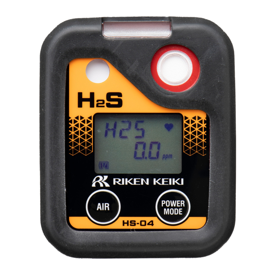
3. Product Configuration 3-2. Part names and functions 3-2. Part names and functions 3-2-1. Main unit ① Alarm lamp/ Infrared communication port ② Buzzer sound ⑨ Battery ⑧ Belt clip ⑥ Sensor opening cover ③ LCD display ④ AIR button ⑦... - Page 26 3. Product Configuration 3-2. Part names and functions Name Function Performs air calibration in measurement mode. Used to select functions when in user AIR button ④ mode, etc. POWER/MODE Turns the power on/off. Confirms operations when in user mode, etc. ⑤...
-
Page 27: Lcd Display
3. Product Configuration 3-2. Part names and functions 3-2-2. LCD display ③ Operating status ① Gas name/ display concentration display ② Battery level ④ Information display icon Name Function Gas name/ ① Displays the detection target gas name and gas concentration. concentration display Battery level icon Indicates battery levels. -
Page 28: Inserting The Batteries
3. Product Configuration 3-3. Inserting the batteries 3-3. Inserting the batteries When using the product for the first time or when battery levels are low, insert/replace with two new batteries. The battery types are as follows: <Dry cell specifications> Japan models: Power source: 3 V DC, 1 mA (Toshiba LR03 battery ×... - Page 29 3. Product Configuration 3-3. Inserting the batteries 3 Remove the old batteries, then insert new batteries. Note the polarity. When removing the batteries, push the [+] end toward the [−] end and then lift out. Remove the batteries one at a time. When inserting the batteries, match the polarity [+] end [+] end...
- Page 30 3. Product Configuration 3-3. Inserting the batteries WARNING An OVER alarm may occur if the power is turned on within 10 minutes of replacing the batteries or the sensor. This is due to the characteristics of the sensor. If an OVER alarm occurs in fresh air after replacing the batteries or the sensor, turn off the power, then turn the power on again after waiting at least 10 minutes.
- Page 31 3. Product Configuration 3-3. Inserting the batteries CAUTION OX G NO2 HCN The sensor will take about five minutes to stabilize after the batteries are replaced. After replacing the batteries, wait at least five minutes before using the product. CAUTION ...
-
Page 32: Alarm Functions
4. Alarm Functions 4-1. Gas alarm types and alarm setpoints Alarm Functions 4-1. Gas alarm types and alarm setpoints OX G A gas alarm is triggered if the concentration of the detected gas reaches or exceeds the alarm setpoints shown in the following table. - Page 33 4. Alarm Functions 4-1. Gas alarm types and alarm setpoints A gas alarm is triggered if the concentration of the detected gas reaches or exceeds the alarm setpoints shown in the following table. (Japan models: Auto reset/Export models: Self-latching) Gas alarm types include the first alarm (WARNING), second alarm (ALARM), third alarm (ALARM H), STEL alarm (STEL), integrated alarm (A-1H) or TWA alarm (TWA) , and OVER alarm (OVER).
- Page 34 4. Alarm Functions 4-1. Gas alarm types and alarm setpoints A gas alarm is triggered if the concentration of the detected gas reaches or exceeds the alarm setpoints shown in the following table. (Japan models: Auto reset/Export models: Self-latching) Gas alarm types include the first alarm (WARNING), second alarm (ALARM), third alarm (ALARM H), STEL alarm (STEL), integrated alarm (A-1H) or TWA alarm (TWA) , and OVER alarm (OVER).
- Page 35 4. Alarm Functions 4-1. Gas alarm types and alarm setpoints A gas alarm is triggered if the concentration of the detected gas reaches or exceeds the alarm setpoints shown in the following table. (Self-latching) Gas alarm types include the first alarm (WARNING), second alarm (ALARM), third alarm (ALARM H), STEL alarm (STEL), TWA alarm (TWA), and OVER alarm (OVER).
- Page 36 4. Alarm Functions 4-1. Gas alarm types and alarm setpoints A gas alarm is triggered if the concentration of the detected gas reaches or exceeds the alarm setpoints shown in the following table. (Self-latching) Gas alarm types include the first alarm (WARNING), second alarm (ALARM), third alarm (ALARM H), STEL alarm (STEL), TWA alarm (TWA), and OVER alarm (OVER).
-
Page 37: Gas Alarm Activation
4. Alarm Functions 4-2. Gas alarm activation 4-2. Gas alarm activation <Buzzer and alarm lamp patterns> When a gas alarm occurs, the user will be alerted by the audible buzzer, flashing alarm lamp, and vibration. The behavior differs depending on the type of alarm. First alarm Second alarm Third alarm... - Page 38 4. Alarm Functions 4-2. Gas alarm activation <Gas alarm display> When a gas alarm occurs, the alarm type is indicated on the LCD display and the corresponding gas concentration display blinks. Display example: Carbon monoxide (CO) concentration: 200 ppm when the third alarm is triggered NOTE ...
-
Page 39: Fault Alarm Activation
If a fault alarm occurs, determine the cause and take appropriate action. If the problem lies with the product and the fault occurs repeatedly, contact Riken Keiki immediately. In the event of a fault alarm, the user will be alerted by the audible buzzer and flashing alarm lamp. -
Page 40: Outside Operating Temperature Range Warning
4. Alarm Functions 4-4. Outside operating temperature range warning 4-4. Outside operating temperature range warning An outside operating temperature range warning (temperature range error) will be issued if a product (other than the OX-04G) is used for 20 minutes or more outside the operating temperature range. When a temperature range error occurs, either leave the product for five minutes or longer in the operating temperature range, or turn off the power of the main unit. -
Page 41: Usage Instrucions
5. Usage Instrucions 5-1. Usage note Usage Instrucions 5-1. Usage note Observe all usage precautions when using the product. Failure to comply with these precautions may result in failure of the product or inability to perform normal gas measurement. 5-2. Preparing startup Check the following before starting gas detection: ... -
Page 42: Turning On The Power
5. Usage Instrucions 5-3. Turning on the power 5-3. Turning on the power Turn the power on and start the product. When the power is turned on, various information, including date and time and alarm setpoints, will be displayed in sequence, followed by the measurement mode screen. - Page 43 5. Usage Instrucions 5-3. Turning on the power OX G (Startup time: OX-04G, approx. 20 seconds; OX-04, approx. 40 seconds) Entire LCD display Calibration Battery level/ Detection target Date and time lights up. notification alarm pattern gas name The buzzer blips once, and the power turns on.
- Page 44 5. Usage Instrucions 5-3. Turning on the power NO2 HCN (Startup time: approx. 20 seconds) (Display example: CO-04) Entire LCD Calibration Battery level/ Detection target Date and time display lights up. notification alarm pattern gas name The buzzer blips once, and the power turns on.
- Page 45 5. Usage Instrucions 5-3. Turning on the power (Startup time: approx. 20 seconds) Entire LCD Calibration Battery level/ Detection target Date and time display lights up. notification alarm pattern gas name The buzzer blips once, and the power turns on. First gas alarm Second gas Third gas alarm...
- Page 46 5. Usage Instrucions 5-3. Turning on the power <Basic operation flow> After turning on the power, the product performs as follows when you press the AIR button or the POWER/MODE button. OX G NO2 HCN (Display example: CO-04) <Air calibration> <Display mode>...
- Page 47 5. Usage Instrucions 5-3. Turning on the power <Display mode> <Air calibration> AIR button POWER/ <Measurement mode> Hold down MODE button POWER/ POWER/ MODE button MODE button <Gas alarm state> <Fault alarm state> 47 / 79...
-
Page 48: Performing Air Calibration
5. Usage Instrucions 5-4. Performing air calibration 5-4. Performing air calibration Perform air calibration before measuring gas concentration. Air calibration refers to zero adjustment required to ensure accurate measurement of gas concentrations. WARNING When air calibration is performed in the atmosphere, check the atmosphere for freshness before starting. The presence of interference gases will prevent proper air calibration. - Page 49 5. Usage Instrucions 5-4. Performing air calibration CAUTION OX G Perform air calibration in an environment that meets all of the following conditions: ・ Pressures, temperatures, and humidity levels are similar to pressures, temperatures, and humidity levels in the actual usage environment.
- Page 50 5. Usage Instrucions 5-4. Performing air calibration NOTE If air calibration fails, [FAIL AIR] will appear. Air calibration will not be performed. Press the POWER/MODE button to reset the fault alarm (calibration abnormality). Resetting the alarm displays the value before air calibration. ...
-
Page 51: Measuring Gas Concentration
5. Usage Instrucions 5-5. Measuring gas concentration 5-5. Measuring gas concentration The product automatically returns to measurement mode once air calibration has been successfully completed to measure the gas concentration. The gas concentration will appear on the LCD display when measurement is complete. If the gas concentration detected reaches the alarm setpoint at this time, a gas alarm is triggered. - Page 52 5. Usage Instrucions 5-5. Measuring gas concentration NOTE When the confirmation beep has been set, the buzzer sounds at the set interval during measurement. (Refer to ‘6-7. Confirmation beep setting (BEEP)’ in the Technical Manual.) The gas concentration alarm setpoints can be checked in display mode. (Refer to ‘5-6. Checking the gas concentration, alarm setpoints, etc.
-
Page 53: Checking The Gas Concentration, Alarm Setpoints, Etc. (Display Mode)
5. Usage Instrucions 5-6. Checking the gas concentration, alarm setpoints, etc. (display mode) 5-6. Checking the gas concentration, alarm setpoints, etc. (display mode) Check measurement results. Switch to display mode to check items like maximum concentration of gas detected, alarm setpoints, date and time, and temperature. -
Page 54: Items Displayed In Display Mode
5. Usage Instrucions 5-6. Checking the gas concentration, alarm setpoints, etc. (display mode) NOTE The product returns automatically to measurement mode if no button operations occur for about 20 seconds. When display mode item display setting (DISP.SET) is OFF, the buzzer volume setting is not displayed. To end display mode, press the POWER/MODE button in the alarm setpoint display screen. - Page 55 5. Usage Instrucions 5-6. Checking the gas concentration, alarm setpoints, etc. (display mode) PEAK Displays the minimum gas concentration display detected since the power was turned on. (Lower You can clear the PEAK value (lower limit limit value) value) displayed, by holding down the AIR ―...
- Page 56 5. Usage Instrucions 5-6. Checking the gas concentration, alarm setpoints, etc. (display mode) Integrated Displays the integrated gas concentration display or value or the TWA value The integrated value (A-1H) is the time- weighted average for gas concentration over display one hour.
- Page 57 5. Usage Instrucions 5-6. Checking the gas concentration, alarm setpoints, etc. (display mode) Displays alarm setpoints. Pressing the AIR Alarm button lets you change the alarm setpoint setpoint display. display [OX-04G, OX-04] Pressing the AIR button cycles through the settings in the following order: [F.S.] (FULL SCALE) →...
- Page 58 5. Usage Instrucions 5-6. Checking the gas concentration, alarm setpoints, etc. (display mode) * HS-04, SC-04 (SO2, NO2, HCN): TWA display *CO-04, CO-04 (C-): Japan models: Integrated (A-1H) display/ Export models: TWA display [CX-04] Pressing the AIR button cycles through the settings in the following order: [F.S.] (FULL SCALE) →...
-
Page 59: Turning Off The Power
5. Usage Instrucions 5-7. Turning off the power NOTE By pressing the AIR button and the POWER/MODE button at the same time while displaying any of the alarm setpoints in the alarm setpoint display of display mode, you can test the relevant alarm. (Refer to ‘7-4. -
Page 60: User Mode Settings
6. User Mode Settings 6-1. User mode setting procedure User Mode Settings 6-1. User mode setting procedure Set the date and time, alarm setpoints, and other settings in user mode. <Displaying the user mode setting screen> Select the setting item in the user mode menu, then make the settings in the setting screen displayed. 1 Turn off the power. - Page 61 6. User Mode Settings 6-1. User mode setting procedure A password input screen will appear if a user mode password was set. Press the AIR button for each digit to enter the password, then press the POWER/MODE button. The user mode menu will appear when you press the POWER/MODE button after entering the 4th digit.
- Page 62 6. User Mode Settings 6-1. User mode setting procedure <Ending user mode> 1 Once the settings are finished, press the AIR button several times to select [START], then press the POWER/MODE button. User mode ends. The product returns to measurement mode after performing the same operation as when the power is turned on.
-
Page 63: User Mode Setting Items
6. User Mode Settings 6-2. User mode setting items 6-2. User mode setting items The following items can be set in user mode: Item LCD display Details Bump test Perform a bump test (function check). (BUMP) The bump test is a test for checking whether the readings are within the acceptable range by introducing a calibration gas. - Page 64 6. User Mode Settings 6-2. User mode setting items Alarm setpoint Set alarm setpoints . You can also return the alarm setpoints to their setting default settings. (ALARM-P) *1 The following alarm setpoints can be set: ・ OX-04G, OX-04: First to third alarm setpoints ・...
- Page 65 6. User Mode Settings 6-2. User mode setting items Confirmation beep Toggle the confirmation beep ON/OFF, set its behavior, and set setting intervals. (BEEP) This function provides an audible indication of whether the product is operating normally. If the bump test expiration setting (BP.RMDR) or the calibration expiration setting (CAL.RMDR) is ON, you can have this function operate when the expiration date is reached.
- Page 66 6. User Mode Settings 6-2. User mode setting items Quick calibration Set the time for quick calibration. time setting The quick calibration function performs AUTO calibration after the (E-CAL) introduction of the calibration gas by automatically counting down the calibration time set with the quick calibration time setting (E-CAL). Date and time Set the date and time for the internal clock.
-
Page 67: Maintenance
7. Maintenance 7-1. Maintenance intervals and maintenance items Maintenance The product is an important safety and disaster-prevention device. Perform product maintenance at regular intervals to ensure performance and to improve disaster-prevention and safety reliability. 7-1. Maintenance intervals and maintenance items Maintain the following items at regular intervals: ... - Page 68 When using the SC-04 (HCN), dirt on the face in contact with the CF-A13D-3 does not pose issues. NOTE Calibration requires dedicated tools and the preparation of a calibration gas. Contact Riken Keiki before performing calibration. The built-in sensor has an expiration date. Replace periodically.
-
Page 69: Storage And Disposal
8. Storage and Disposal 8-1. Procedures for storage or when not in use for extended periods Storage and Disposal 8-1. Procedures for storage or when not in use for extended periods The product must be stored in the following environment: ... -
Page 70: Product Disposal
8. Storage and Disposal 8-2. Product disposal 8-2. Product disposal Dispose of the product as industrial waste (incombustible) in accordance with local regulations. WARNING Dispose of batteries in accordance with procedures specified by local authorities. <Disposal in EU member states> When disposing of the product in an EU member state, dispose of the batteries separately. -
Page 71: Troubleshooting
A circuit abnormality Contact Riken Keiki for repair. [FAIL SYSTEM] appears. occurred in the main unit. Contact Riken Keiki to request sensor replacement. Sensor abnormality: The sensor sensitivity has (Refer to ‘7-6-3. Sensor replacement’ in the Technical [FAIL SENSOR] appears. - Page 72 Fresh air is not being Supply fresh air around the product. supplied to the product. Air calibration is not possible. Contact Riken Keiki to request sensor replacement. The sensor sensitivity has [FAIL AIR] appears. (Refer to ‘7-6-3. Sensor replacement’ in the Technical degraded.
- Page 73 If problems persist even after taking the corrective actions suggested here or if you encounter symptoms not listed here, contact Riken Keiki. 73 / 79...
-
Page 74: Product Specifications
10. Product Specifications 10-1. Common specifications Product Specifications 10-1. Common specifications display LCD digital display (segments + icons) Sampling method Diffusion type Gas alarm Three-step alarm, STEL alarm, integrated (for CO models only, Japan models only) or TWA alarm, OVER alarm Fault alarm Sensor connection/disconnection, low battery voltage, faulty calibration, clock abnormality, system abnormality... - Page 75 10. Product Specifications 10-1. Common specifications Explosion-proof class <Dry cell specifications> Certificate of conformity for electrical equipment used in potentially explosive atmospheres: Ex ia IIC T4 Ga ATEX: II 1G Ex ia IIC T4 Ga IECEx: Ex ia IIC T4 Ga <Rechargeable battery specifications>...
-
Page 76: Specifications By Model
10. Product Specifications 10-2. Specifications by model 10-2. Specifications by model Model OX-04G OX-04 HS-04 CO-04 CO-04 (C-) CX-04 Carbon monoxide Detection target Carbon Oxygen Oxygen Hydrogen sulfide (reduced hydrogen Carbon monoxide Oxygen monoxide interference) Detection Galvanic cell Electrochemical type^ principle type Display name... - Page 77 10. Product Specifications 10-2. Specifications by model Alarm permitted L/LL 0.0 to 20.0 % L/LL 0.0 to 20.0 % 1.0 to 200.0 ppm 20 to 2,000 ppm 20 to 2,000 ppm setting range 21.8 to 40.0 % 21.8 to 40.0 % Within Within Within...
- Page 78 10. Product Specifications 10-2. Specifications by model Model SC-04 (SO2) SC-04 (NO2) SC-04 (HCN) Detection target Sulfur dioxide Nitrogen dioxide Hydrogen cyanide Detection Electrochemical type principle Display name Sensor model ESR-A13D ESR-A13D ESR-A13D Display range 0.00 to 100.00 ppm 0.00 to 20.00 ppm 0.0 to 30.0 ppm (resolution) (0.05)
- Page 79 10. Product Specifications 10-2. Specifications by model Operating 0 to 95 %RH (under temporary use environment for approx. 15 minutes) humidity range 10 to 90 %RH (under continuous use environment) (no condensation) Operating 80 kPa to 120 kPa (80 kPa to 110 kPa for explosion-proof range) pressure range Continuous operating time...
- Page 80 Revision History Revision History Issue Revision details Issue date First issue 01/23/2020 *Corresponds to Technical Manual PT0-1940. Added 1-4. Checking standards and explosion-proof 04/09/2020 specifications/Changed CF-1821 to CF-6280 (CO-04, CX-04)/Other amendments made to wording *Corresponds to Technical Manual PT0E-1941. Revised 2-4. Safety information/Added description to 10-2. Specifications 11/25/2020 by model/Added “SC-04 (NO2, HCN)”/modified “SC-04 (SO2) alarm setting range”...
Need help?
Do you have a question about the 04 Series and is the answer not in the manual?
Questions and answers