Advertisement
Quick Links
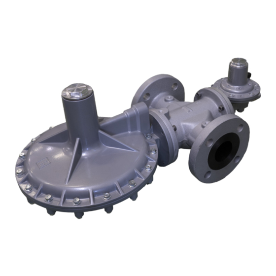
Cirval
Installation and
commisioning guide
This document is a guide for the installation and commissioning of Cirval regulator. It is compulsory to read the
complete operation, maintenance and warning manual before working on the device.
Full operation, maintenance and warning manual can be found on the PIETRO FIORENTINI S.P.A. website.
1.1 -
GENERAL SAFETY WARNINGS
The equipment described in this manual is:
•
a device subject to pressure in pressurized systems;
•
normally included in systems transporting flammable gases (for example: natural gas).
If the gas used is a combustible gas, the area where the equipment is installed is called a "danger zone" because
there are residual risks of the formation of potentially explosive atmospheres.
In and around "danger zones" it is absolutely:
•
necessary there are no effective ignition sources present;
•
prohibited to smoke.
Authorized operators shall not perform operations or interventions on their own initiative that are not within their
competence.
Never work on the equipment:
•
Under the influence of exciting substances such as, for example, alcohol;
•
In the case of using drugs that can lengthen reaction time.
The employer must train and inform operators on how to behave during operations and what equipment to use.
Before installation, commissioning or maintenance, operators must:
•
Take note of the safety regulations applicable to the installation site where they are to operate;
•
Obtain, when required, the necessary authorizations to operate;
•
Equip themselves with the necessary individual safeguards required in the procedures described in this manual;
•
Ensure that the area in which they are to work is equipped with the required collective protections and necessary safety signs.
1.2 -
GENERAL INFORMATION ABOUT CONNECTIONS
The equipment must be installed in the line with the arrow on the body facing in the direction of gas flow. The on-line installation must include:
Pos.
Description
1
no.1 shut-off valve upstream of the equipment.
2
no. 2 vent valves placed one upstream and one downstream of the equipment.
3
no. 2 pressure gauges placed one upstream and one downstream of the equipment.
4
no. 1 pressure regulator.
5
no. 1 shut-off valve downstream of the equipment.
Fig. 1.1. In-line Installation
When the device is used in gas pressure reduction stations, it must be installed at least according to the require-
ments of UNI EN 12186:2014 or UNI EN 12279:2007.
The vents of the equipment must be channeled according to UNI EN 12186: 2014 or UNI EN 12279: 2007 or the
standards in force at the place of installation of the equipment.
All the equipments used in the commissioning procedures are shown in chapter 1.11.
HEADQUARTERS
Pietro Fiorentini S.pA. via E. Fermi 8/10 36057 Arcugnano (VI) ITALY
1.3 -
CIRVAL INSTALLATION PROCEDURES
Step
Operation
1
Place the equipment in the section of the line used for it.
2
Place gaskets between the line flanges and the regulator flanges.
3
Insert the bolts into the appropriate holes in the connecting flanges.
4
Screw the bolts following the technical rules for tightening the flanges.
For installation carried out after maintenance, replace the gaskets.
1.4 -
REGULATOR COMMISSIONING PROCEDURE
In the application consisting of multiple parallel pressure control lines, it is recommended to commission one line at a time starting with the one with the
lowest set-point. The set-point value is recalled on the test certificate attached to each piece of equipment.
Step
Operation
1
Partially open the vent valve.
Very slowly open the upstream shut-off valve.
2
3
Check the pressure of the line inlet pipe by referring to the upstream pressure gauge.
To adjust the regulator to the required set-point value, remove the spring cap and turn the adjustment nut:
•
clockwise to increase the pressure value;
•
counterclockwise to decrease the pressure value.
4
5
Place and secure the spring cap.
6
Close the vent valve.
7
Check that the downstream pressure and make sure the regulator locks up and the pressure does not build.
8
Check with a foaming substance the tightness of all joints located between the shut-off valves.
Very slowly open the downstream shut-off valve until the pipeline is completely filled.
9
1.5 -
COMMISSIONING OF THE CIRVAL + IN LINE MONITOR OPERATION
Step
Operation
1
Remove the spring cap from the main regulator.
2
Remove the spring cap from the regulator in inline monitor function.
3
Partially open the vent valve.
Very slowly open the upstream shut-off valve, checking that the downstream pressure (Pd) indicated by the downstream pressure gauge
4
(5) does not exceed the required setting value by more than 50%.
5
Check the pressure of the line inlet pipe by referring to the upstream pressure gauge.
6
Insert and tighten the Q key (chapter 1.11) in the slot of the cap to fully open the main regulator.
To adjust the in-line monitor regulator to the required set-point value turn the adjustment nut:
•
clockwise to increase the pressure value;
•
counterclockwise to decrease the pressure value.
7
8
Close the vent valve.
9
Check that the downstream pressureand make sure the regulator locks up and the pressure does not build.
10
Partially open the vent valve.
11
Unscrew and remove the Q key (chapter 1.11) from the slot of the cap.
Check that the set-point pressure of the main regulator is at the set value by referring to the pressure value indicated by the downstream
12
pressure gauge.
Verify that the regulator with inline monitor function is fully open (100%).
Fig. 1.2. Square installation
13
14
Close the vent valve.
Check that the downstream pressureand make sure the regulator locks up and the pressure does not build (refer to the nameplate SG
15
value).
16
Install and tighten spring cap on the main regulator.
17
Install and tighten spring cap on the in-line monitor regulator.
18
Check with a foaming substance the tightness of all joints located between the shut-off valves.
US REPRESENTATIVE
Pietro Fiorentini USA, Inc. 606 Park Drive Weirton, WV 26062
Check the pressure by referring to the pressure gauge located upstream.
Check the pressure by referring to the pressure gauge located downstream.
•
If the pressure of the downstream pipeline is lower than the set-point pressure, partialize the
opening of the downstream shut-off valve so as not to exceed the value of the maximum flow
rate of the system.
•
Check the pressure by referring to the downstream pressure gauge.
Check the pressure by referring to the pressure gauge located downstream.
The monitor regulator is fully open, when the pressure indicated on the intermediate pressure
gauge is the same as the upstream pressure gauge.
Step
Operation
Slowly open downstream shut-off valve until the pipeline is completely filled.
•
If the pressure of the downstream pipeline is lower than the regulator set point pressure,
19
partially open the downstream shut-off valve so as not to exceed the value of the maximum
flow rate and pressure of the system.
•
Check the pressure by referring to the downstream pressure gauge.
1.6 -
COMMISSIONING OF THE REGULATOR + IFM BUILT-IN MONITOR
In the application consisting of multiple parallel pressure control lines, it is recommended to commission one line at a time starting with the one with the
lowest set-point. The set-point value is recalled on the test certificate attached to each piece of equipment.
Step
Operation
1
Remove the spring cap from the main regulator.
2
Remove the spring cap from the built-in IFM monitor.
3
Partially open the vent valve.
Very slowly open the upstream shut-off valve, checking that the downstream pressure (Pd) indicated by the downstream pressure gauge
4
does not exceed the required setting value by more than 50%.
5
Check the pressure of the line inlet pipe by referring to the upstream pressure gauge.
6
Insert and tighten the Q key (chapter 1.11) in the slot of the cap to fully open the main regulator.
To adjust the set point of the built-in IFM monitor turn the adjustment nut:
•
clockwise to increase the pressure value;
•
counterclockwise to decrease the pressure value.
7
Check the pressure by referring to the pressure gauge located downstream.
8
Close the vent valve.
9
Check that the downstream pressure and make sure the regulator locks up and the pressure does not build.
10
Partially open the vent valve.
11
Unscrew and remove the Q key (chapter 1.11) from the slot of the cap.
Check that the set-point pressure of the main regulator is at the preset value by referring to the pressure value indicated by the downstream
12
pressure gauge.
13
Close the vent valve.
Check that the downstream pressure (Pd), after an increment phase, does not exceed the closing pressure value of the main regulator (refer
14
to the nameplate SG value).
15
Insert the spring cap into the main regulator.
16
Insert the spring cap into the built-in IFM monitor.
17
Check with a leak foaming substance the tightness of all joints located between the shut-off valves.
Slowly open downstream shut-off valve until the pipeline is completely filled.
•
If the pressure of the downstream pipeline is lower than the set-point, partially open the
18
downstream shut-off valve so as not to exceed the set-point of the maximum flow rate of the
system.
•
Check the pressure by referring to the downstream pressure gauge.
1.7 -
COMMISSIONING OF THE REGULATOR + IMD BUILT-IN MONITOR
In the application consisting of several pressure control lines, it is recommended to commission one line at a time starting with the one with the lowest
set-point. The set-point value is recalled on the test certificate attached to each piece of equipment.
Step
Operation
1
Remove the spring cap from the main regulator.
2
Partially open the vent valve.
Very slowly open the upstream shut-off valve, checking that the downstream pressure (Pd) indicated by the downstream pressure gauge
3
does not exceed the required setting value by more than 50%.
4
Check the pressure of the line inlet pipe by referring to the upstream pressure gauge.
5
Insert and tighten the Q key (chapter 1.11) in the slot of the cap to fully open the main regulator.
6
Check the set-point value of the built-in IMD monitor by referring to the downstream pressure gauge.
Check the controlled escape of gas from the vent valve.
7
Check with foaming solution.
8
Close the vent valve.
9
Check that the downstream pressure and make sure the regulator locks up and the pressure does not build.
Check the controlled escape of gas from the vent.
10
Check with foaming solution.
11
Partially open the vent valve.
12
Unscrew and remove the Q key (chapter 1.11) from the slot of the cap.
ITALY +39 0444 968 511
USA +1 304 232 9115
www.fiorentini.com
sales@fiorentini.com
Advertisement

Subscribe to Our Youtube Channel
Related Manuals for PIETRO FIORENTINI Cirval 200


Summary of Contents for PIETRO FIORENTINI Cirval 200
- Page 1 Very slowly open the upstream shut-off valve, checking that the downstream pressure (Pd) indicated by the downstream pressure gauge Full operation, maintenance and warning manual can be found on the PIETRO FIORENTINI S.P.A. website. Partially open the vent valve.
- Page 2 Arming the slam-shut valve by pulling down the reset knob. Check the pressure switch settings of the LA slam-shut valve by referring to Section 1.8.3. • Cirval 200: 1" 1/4, 1" 1/2 and 2" NPT according to ANSI B1.20.1 Close the vent valve. Tubing Connections •...
Need help?
Do you have a question about the Cirval 200 and is the answer not in the manual?
Questions and answers