
Related Manuals for PIETRO FIORENTINI PVS 782


Summary of Contents for PIETRO FIORENTINI PVS 782
- Page 1 SAFETY/RELIEF VALVE PVS 782 TECHNICAL MANUAL MT 014 INSTRUCTIONS FOR THE INSTALLATION, ENTRY INTO SERVICE AND MAINTENANCE | sales@mvandc.com | Phone: 877.566.3837 | Fax: 925.407.2903 www.mvandc.com...
-
Page 2: Table Of Contents
TABLE OF CONTENTS 1.0 INTRODUCTION 1.1 MAIN SPECIFICATIONS 1.2 VALVE CONTROL 1.3 DESCRIPTION OF THE OPERATION 1.4 VALVE SIZING 2.0 INSTALLATION 2.1 GENERAL WARNINGS 2.2 GENERAL REQUIREMENTS 2.3 SPECIAL REQUIREMENTS 2.4 CONDITIONS OF USE 3.0 COMMISSIONING 3.1 PRESSURIZZATION 3.2 INSPECTION OF THE EXTERNAL TIGHTNESS 3.3 INSPECTION OF THE INTERNAL TIGHTNESS 3.4 COMMISSIONING (INSTALLATION ACCORDING TO DIAGRAM IN FIG. -
Page 3: Introduction
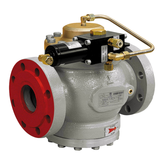
In FIGURE 1 the valve functional diagram is illustrated. 1.1 MAIN SPECIFICATIONS The PVS 782 valves are safety accessories fit for the use on preliminary treated non aggressive gaseous fluids. Such valves may be installed both on pipelines and on pressure vessels. - Page 4 Figure 1 | sales@mvandc.com | Phone: 877.566.3837 | Fax: 925.407.2903...
-
Page 5: Valve Control
(15) spring 1.2 VALVE CONTROL The PVS 782 valve is a pilot-operated valve therefore the valve opening and closing operations are controlled by a pilot device. The below listed pilot devices are available: Pilot P 15/A field of intervention1,5 – 43 bar ( see figure 2 );... - Page 6 Figure 2 | sales@mvandc.com | Phone: 877.566.3837 | Fax: 925.407.2903...
-
Page 7: Description Of The Operation
1.3 DESCRIPTION OF THE OPERATION Make reference to figure 1. Under ordinary conditions the controlled pressure, that is the valve inlet pressure reaches the pilot chamber (A) and (C) (1) through the connection pipe (1) and the filter (2), and, through the nozzle (3) it reaches the valve main chamber (B). -
Page 8: Valve Sizing
(8) on its seal seat 1.4 VALVE SIZING The PVS 782 valve is sized by means of the formula reported on the RACCOLTA E chapter E. 1. D. that is q = ( 0,9 x K ) x (394,9 x C ) x P... -
Page 9: Installation
k = coefficient of the isentropic equation Table 1 Dimension 1” 1” ½ 2” 2” ½ 3” 4” 6” 8” Area cm 5,31 13,85 22,89 35,24 54,08 102,02 203,48 359,50 2. INSTALLATION 2.1 GENERAL WARNINGS Before the installation , commissioning, or maintenance, the operators shall: - examine the safety devices applicable to the installation where they have to work - obtain the necessary authorizations to work, when required - equip oneself with the necessary individual protections ( helmet, goggles, etc.. - Page 10 2.2 GENERAL INSTRUCTIONS The valve installation shall be carried out in compliance with the prescriptions (laws or regulations) in force in the place of installation. In particular the specifications of natural gas plants shall be in compliance with the law provisions or regulations in force in the place of installation, or at least in compliance with the EN 12186 or EN12279 regulations (we remind that the installation in compliance with such laws minimizes the risk of fire hazard).
- Page 11 The valves placed upstream from the valve, if any, shall be of a total flow type, so that the discharge capacity is not limited. Connect the pilot sensing line by means of compression fittings, according to the plant specifications. In case the plant specifications require it, connect the pilot vent to the specific drain pipe. On the valve drain pipe arrange a protection end against water and nesting The connections to the inlet and outlet pipelines are carried out by means of standardized flanges the sizes and types of which are showed on the data plate ( see chapter 2.4 );...
- Page 12 Legend of Figure Dimensioni d’ingombro: overall dimensions, peso in kg: weight in Kg | sales@mvandc.com | Phone: 877.566.3837 | Fax: 925.407.2903...
- Page 13 Figure 3 Not included in our supply, Discharge to the atmosphere, Cut-off valve | sales@mvandc.com | Phone: 877.566.3837 | Fax: 925.407.2903...
- Page 14 Figure 4 | sales@mvandc.com | Phone: 877.566.3837 | Fax: 925.407.2903...
-
Page 15: Conditions Of Use
2.4 CONDITIONS OF USE We recommend to check, before commissioning, that the conditions of use are in compliance with the equipment specifications. Such specifications are reported on the identification plates of each valve (figure 5). Figure 5 The meaning of the symbols written on the plate is the following Safety valve valve model flow rate coefficient ( where foreseen ) -
Page 16: Commissioning
inlet pressure field Pemax max inlet pressure total intervention field specific intervention pressure field with inserted spring In particular we would like you to draw your attention to the following specifications: - PS max. permissible pressure. - TS design temperature (the minimum and maximum values are shown). - the inlet and outlet connections class. -
Page 17: Commissioning (Installation According To Diagram In Fig. 3)
3.3 CONTROL OF THE INTERNAL TIGHTNESS The valve internal tightness may be checked by placing the valve in full close position, keeping the line pressure upstream from the valve and checking that there is not fluid leaks downstream from the valve and from the pilot blowdown. 3. -
Page 18: Maintenance
Moreover, make sure to be have a series of recommended spare parts. The spare parts shall be Pietro Fiorentini Spa genuine spare parts. NOTE. The use of non genuine spare parts relieves the manufacturer from any liability. | sales@mvandc.com | Phone: 877.566.3837 | Fax: 925.407.2903... -
Page 19: Disassembly
4.2 DISASSEMBLY For the disassembly no special wrenches are required. Before carrying out the disassembly, put some reference signs on the elements of the pilot that connect it to the valve It is necessary to pay particular attention in order not to damage the valve and the o’rings seats. -
Page 20: Storage
6.0 STORAGE The PVS 782 valves do not require specific precautions in case of storage for long periods; anyway it is recommended to pay attention to: - keep the valves in the original packing; - keep the protections applied in the factory on the flanged connections;...
Need help?
Do you have a question about the PVS 782 and is the answer not in the manual?
Questions and answers