
Related Manuals for PIETRO FIORENTINI VS/AM 58 Series


Summary of Contents for PIETRO FIORENTINI VS/AM 58 Series
- Page 1 VS/AM 58 Relief valve Revision A - Edition 05/2023 USE, MAINTENANCE AND WARNING MANUAL...
- Page 2 RELIEF VALVE INTRODUCTION REV. A Use, maintenance and warning manual...
-
Page 3: Introduction
Training the personnel in charge is essential in order to: • the use and maintenance of the device in the correct manner; • correctly apply the safety alerts and recommended procedures. Revision: A COPYRIGHT 2023 © PIETRO FIORENTINI S.P.A. RELIEF VALVE INTRODUCTION REV. A Use, maintenance and warning manual... - Page 4 RELIEF VALVE INTRODUCTION REV. A Use, maintenance and warning manual...
-
Page 5: Revision History
1.1 - REVISION HISTORY Revision Date Revision contents index 05/2023 First issue Tab. 1.1. RELIEF VALVE INTRODUCTION REV. A Use, maintenance and warning manual... -
Page 6: Table Of Contents
INDICE 1 - INTRODUCTION ........................3 1.1 - REVISION HISTORY ..........................5 2 - GENERAL INFORMATION ....................9 2.1 - MANUFACTURER IDENTIFICATION ......................9 2.2 - IDENTIFICATION OF THE PRODUCT ......................9 2.3 - REGULATORY FRAMEWORK ........................9 2.4 - WARRANTY ............................10 2.5 - SYMBOLS USED IN THE MANUAL ...................... - Page 7 5 - TRANSPORT AND HANDLING ..................27 5.1 - SPECIFIC WARNINGS FOR TRANSPORT AND HANDLING ..............27 5.1.1 - PACKAGING AND FASTENERS USED FOR TRANSPORT ..............28 5.2 - PACKAGING CONTENT .......................... 28 5.3 - PHYSICAL CHARACTERISTICS OF THE DEVICE ................... 29 5.3.1 - STANDARD VERSION ...........................29 5.3.2 - FLANGED VERSION ..........................30 5.4 - DEVICE ANCHORING AND LIFTING METHOD ..................
- Page 8 9 - MAINTENANCE AND FUNCTIONAL CHECKS ..............49 9.1 - GENERAL WARNINGS ........................... 49 9.2 - PERIODICALLY CHECKING AND INSPECTING THE EQUIPMENT FOR PROPER OPERATION ....51 9.3 - ROUTINE MAINTENANCE ........................52 9.3.1 - GENERAL SAFETY WARNINGS ......................52 9.3.2 - REPLACEMENT FREQUENCY FOR COMPONENTS SUBJECT TO WEAR ...........52 9.4 - ROUTINE MAINTENANCE PROCEDURES ....................
-
Page 9: General Information
REGULATORY FRAMEWORK PIETRO FIORENTINI S.P.A. with registered office in Arcugnano (Italy) - Via E. Fermi, 8/10, declares under its sole respon- sibility that the VS/AM 58 relief valve covered by this manual, is classified as a safety accessory and is: •... -
Page 10: Warranty
PIETRO FIORENTINI S.P.A. guarantees that the device was manufactured using the best materials, with high quality work- manship, and complies with the quality requirements, specifications and performance set out in the order. The warranty shall be considered null and void and PIETRO FIORENTINI S.P.A. shall not be liable for any damage and/or malfunctions: •... -
Page 11: Addressees, Supply And Storage Of The Manual
Removing, rewriting or editing the pages of the manual and their contents is not allowed. PIETRO FIORENTINI S.p.A. shall not be held liable for any damage to people, animals and property caused by failure to adhere to the warnings and operating procedures described in this manual. -
Page 12: Applied Rating Plates
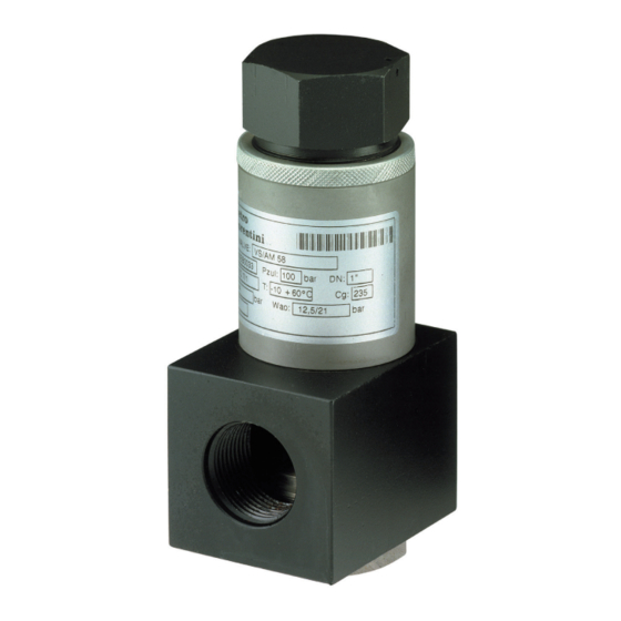
WARNING! Removing nameplates and/or replacing them with other plates is strictly not allowed. Should the plates be unintentionally damaged or removed, the customer must notify PIETRO FIORENTINI S.p.A. The device is equipped with rating plate (A): ID n. ARCUGNANO(VI) - ITALY SAFETY VALVE S.n. -
Page 13: Glossary For Rating Plates
2.8.1 - GLOSSARY FOR RATING PLATES The terms and abbreviations used on rating plates are described in Tab. 2.5: Term Description CE marking ensuring the conformity of the product with the requirements of the applicable EU directives or regulations. Identifier of the body that issued the CE marking. Model Device model. -
Page 14: Qualified Professional Figures
2.10 - QUALIFIED PROFESSIONAL FIGURES Qualified operators in charge of using and managing the device throughout its technical service life: Professional figure Definition Qualified operator able to: • handle materials and equipment; • carry out all the operations necessary to properly install the device; Installer •... -
Page 15: Safety
3 - SAFETY 3.1 - GENERAL SAFETY WARNINGS WARNING! The device described in this manual is: • subject to pressure in pressurised systems; • normally installed in systems carrying flammable gases (for example: natural gas). WARNING! If the gas used is a combustible gas, the installation area of the device is defined as a “danger zone” as there are residual risks that potentially explosive atmospheres may be generated. -
Page 16: Personal Protective Equipment
3.2 - PERSONAL PROTECTIVE EQUIPMENT Tab. 3.8 shows the Personal Protective Equipment (PPE) and its description; an obligation is associated with each symbol. Personal protective equipment means any equipment intended to be worn by the worker in order to protect them against one or several risks that are likely to threaten their safety or health during work. -
Page 17: Residual Risks
WARNING! If there are any functional faults, do not operate. Immediately contact PIETRO FIORENTINI S.p.A. for the necessary directions. In accordance with the requirements of PED Directive 2014/68/EU point 1.2 of Annex I, below is an assessment of the risks associated with the device and an indication of the principles adopted for their prevention, according to the following classification: a) Elimination and/or reduction of the risk. - Page 18 3.3.1 - TABLE SHOWING RESIDUAL RISKS DUE TO PRESSURE WARNING! If there are any functional faults, do not operate. Immediately contact PIETRO FIORENTINI S.p.A. for the necessary directions. Effect and Risk and Hazard Event and Cause Solution and Prevention Consequence Pressurised gas a.
- Page 19 • Deterioration of Projection of • Environments with a. The user must shut off the line and con- external surfaces; metallic and aggressive atmos- tact PIETRO FIORENTINI S.p.A. • Corrosion. non-pressurised phere. parts. Tab. 3.9. RELIEF VALVE SAFETY REV. A...
-
Page 20: Table Of Residual Risks For Potentially Explosive Atmospheres
3.3.2 - TABLE OF RESIDUAL RISKS FOR POTENTIALLY EXPLOSIVE ATMOSPHERES Tab. 3.10 shows the conditions that can lead to the generation of a potentially explosive atmosphere respectively for: • the pressure regulator; • the monitor; • the slam-shut device. The table is valid for use with natural gas with a density of no more than 0.8; for different densities, the installation and environmental conditions must also be evaluated. - Page 21 Potentially Management measures in- Operating explosive Normative references cluded in the instructions for conditions atmosphere use and warning This type of malfunction is not rea- Breakage of other sonably expected as it involves stat- non-metallic parts ic seals (to the outside) that cannot (malfunction) generate any external leakage.
-
Page 22: Obligations And Prohibitions
NOISE LEVEL VS/AM 58 is a safety device with no moving parts. For the value of the noise generated by the device and further information, contact PIETRO FIORENTINI S.p.A. ATTENTION! The obligation to use earmuffs or ear plugs to protect the hearing of qualified professional figures (ref- erence paragraph 2.10) remains in the event that the noise in the installation environment of the device... -
Page 23: Description And Operation
4 - DESCRIPTION AND OPERATION 4.1 - GENERAL DESCRIPTION The relief valves in the VS/AM 58 series are suitable for: • pre-purified gaseous fluids; • medium and low pressure systems. The VS/AM 58 valve is also available as a safety valve. -
Page 24: Operation
Activation of the VS/AM 58 relief valve involves no external control sources other than the fluid itself. The relief valves in the VS/AM 58 series can be installed on both pipelines and pressure vessels. The pressure at the control point may exceed the calibration pressure due to: •... -
Page 25: Intended Use
If no written approval is provided, use shall be considered improper. In the event of “improper use”, PIETRO FIORENTINI S.p.A. shall not be held liable for any damage caused to people or property, and any type of warranty on the device shall be deemed void. -
Page 26: Technical Features/Performance
4.4 - TECHNICAL FEATURES/PERFORMANCE The main technical features of the device are listed at Tab. 4.15: Technical features Maximum allowable pressure up to 100 bar Ambient temperature range from -20°C to + 60°C Inlet gas temperature range from -20°C to + 60°C Minimum flow rate up to 1:100 Accuracy... -
Page 27: Transport And Handling
5 - TRANSPORT AND HANDLING 5.1 - SPECIFIC WARNINGS FOR TRANSPORT AND HANDLING NOTICE! Transport and handling must be carried out in compliance with the regulations in force in the country of installation by personnel who are: • qualified (specially trained); •... -
Page 28: Packaging And Fasteners Used For Transport
PIETRO FIORENTINI S.p.A.. NOTICE! PIETRO FIORENTINI S.p.A. shall not be liable for any damage to people or property caused by accidents due to failure to comply with the instructions provided in this manual. Tab. 5.17 describes the types of packaging used: Ref. -
Page 29: Physical Characteristics Of The Device
5.3 - PHYSICAL CHARACTERISTICS OF THE DEVICE 5.3.1 - STANDARD VERSION Fig. 5.4. Physical characteristics VS/AM 58 standard version VS/AM 58 overall dimensions Nominal diameter [mm] Size [inches] 1” Tab. 5.19. Weights [kgf] Ansi 150 Ansi 300/600 RP / NPT Tab. -
Page 30: Flanged Version
5.3.2 - FLANGED VERSION Fig. 5.5. Physical characteristics VS/AM 58 flanged version VS/AM 58 overall dimensions Flanging ANSI 150 ANSI 300 ANSI 600 Weight [kg] 3,85 5,58 5,59 Tab. 5.21. RELIEF VALVE TRANSPORT AND HANDLING REV. A Use, maintenance and warning manual... -
Page 31: Device Anchoring And Lifting Method
5.4 - DEVICE ANCHORING AND LIFTING METHOD HAZARD! Using lifting equipment (if necessary) for unloading, carrying and handling packages is reserved only for skilled operators who have been properly trained (and are appropriately qualified if required by the regula- tions in force in the country of installation) and are familiar with: •... -
Page 32: Forklift Handling Method
5.4.1 - FORKLIFT HANDLING METHOD HAZARD! It is forbidden to: • Do not transit under suspended loads; • Do not move the load over the personnel operating in the site/plant area. WARNING! The following is not allowed on forklifts: • carrying passengers;... - Page 33 Step Action Image Sollevare lentamente il carico di qualche decina di centimetri e veri carne la stabilità facendo attenzio- Inclinare il montante all’indietro (verso il posto guida) per avvantaggiare il momento ribaltante e Adeguare la velocità d ne che il baricentro del carico sia posizionato al centro delle forche di sollevamento. garantire una maggiore stabilità...
-
Page 34: Packaging Removal
• do not install the equipment; • contact PIETRO FIORENTINI S.p.A. and specify the details provided on the device nameplate. WARNING! The individual device is contained in a specially designed cardboard box. Avoid taking the device out of the box before its installation. -
Page 35: Storage And Environmental Conditions
5.6 - STORAGE AND ENVIRONMENTAL CONDITIONS WARNING! Protect the regulator from blows and impacts, even accidental, until it is installed. The following table shows the minimum environmental conditions to be expected should the device be stored for an ex- tended period. Compliance with these conditions will guarantee the declared performance: Conditions Data... -
Page 36: Installation
6 - INSTALLATION 6.1 - INSTALLATION PRE-REQUISITES 6.1.1 - ALLOWED ENVIRONMENTAL CONDITIONS WARNING! To safely use the device, in full respect of the allowed environmental conditions, follow the data shown on the regulator plate and on any accessories (refer to paragraph 2.8 “Nameplates applied”). WARNING! The device must be installed away from atmospheric agents and direct sunlight. -
Page 37: Checks Before Installation
6.1.3 - CHECKS BEFORE INSTALLATION The device does not require any further upstream safety device for protection against any overpressure with respect to its PS admissible pressure when, for the upstream reduction station, the maximum incidental downstream pressure MIPd ≤ 1.1 PS MIPd = Maximum incidental downstream pressure value (for further information, see UNI EN 12186:2014). -
Page 38: Specific Safety Instructions For The Installation Step
It is the responsibility of the system designer to correctly dimension the discharge line downstream of the device in accordance with the design conditions. WARNING! The installer must use fittings and gaskets recommended by PIETRO FIORENTINI S.p.A. WARNING! In order to avoid breakage or unwanted deformation, it is necessary to: •... -
Page 39: Possible Installations Of The Device
6.3 - POSSIBLE INSTALLATIONS OF THE DEVICE NOTICE! • With natural gas or other non-corrosive gases that are not subject to recondensation, the device can be installed in any flow direction. • Please avoid any mounting positions with outlet flow facing upwards in installations using LPG. For information about how to mount the device in keeping with the available models and configurations, refer to Tab. -
Page 40: Installation Procedure
6.4 - INSTALLATION PROCEDURE Installation Operator qualification • Installer. WARNING! The PPE listed in this table is related to the risk associated with the device. For PPE required the PPE required to protect against risks associated with the workplace, instal- lation or operating conditions, please refer to: •... -
Page 41: Device Installation Procedure
Tab. 6.28. Fig. 6.6. Installation scheme NOTICE! The warranty shall be deemed null and void and PIETRO FIORENTINI S.p.A. shall not be held liable for any damage and/or malfunctions if the fittings used during installation are not those supplied. 6.5 - POST-INSTALLATION CHECKS To perform the post-installation check, proceed as shown in Tab. -
Page 42: Commissioning/Maintenance Equipment
7 - COMMISSIONING/MAINTENANCE EQUIPMENT 7.1 - LIST OF EQUIPMENT Use of commissioning/maintenance equipment • Name of the user. Operator qualification • Specialised technician. WARNING! The PPE listed in this table is related to the risk associated with the device. For PPE required the PPE required to protect against risks associated with the workplace, instal- lation or operating conditions, please refer to:... -
Page 43: Commissioning
8 - COMMISSIONING 8.1 - GENERAL WARNINGS 8.1.1 - SAFETY REQUIREMENTS FOR COMMISSIONING HAZARD! During commissioning the risks associated with any discharges to the atmosphere of flammable or nox- ious gases must be evaluated. HAZARD! In case of installation on distribution networks for natural gas, consider the risk associated with explosive mixtures (gas/air) being formed inside the piping, if the line is not subjected to inerting. -
Page 44: Preliminary Procedures For Commissioning
8.2 - PRELIMINARY PROCEDURES FOR COMMISSIONING HAZARD! Before commissioning the equipment, it must be ensured that any source of explosion has been eliminat- ed if there is such a danger. WARNING! Before commissioning, you need to make sure that the characteristics of the equipment are suitable for the conditions of use. -
Page 45: Proper Commissioning Check
8.3 - PROPER COMMISSIONING CHECK Completely sprinkle the equipment with a foaming solution (or equivalent control system) in order to check the tightness of the external surfaces of the regulator and the connections made during the installation. 8.4 - CALIBRATION OF EQUIPMENT AND ACCESSORIES INSTALLED NOTICE! To properly calibrate the equipment and accessories present, refer to the accuracy class indicated on the nameplates (see section “2.8 - Applied rating plates”). -
Page 46: Relief Valve Commissioning Procedure Vs/Am 58
8.5 - RELIEF VALVE COMMISSIONING PROCEDURE VS/AM 58 8.5.1 - WITH EXTERNAL PRESSURE SOURCE Fig. 8.7. Commissioning VS/AM 58 with shut-off valve RELIEF VALVE COMMISSIONING REV. A Use, maintenance and warning manual... - Page 47 Step Action Check that the upstream (V1) and downstream (V2) shut-off valves are closed. Partially open the bleed cock (6). Disconnect the downstream pipe connected to the relief valve (7). Connect the external source (3) upstream of the equipment (2). NOTICE! Check the pressure referring to the upstream pressure gauge (4).
-
Page 48: Without External Pressure Source
8.5.2 - WITHOUT EXTERNAL PRESSURE SOURCE Fig. 8.8. Relief valve commissioning VS/AM 58 without shut-off valve Step Action Close the downstream shut-off valve (V2). Disconnect the downstream pipe connected to the relief valve (7). Increase the upstream pressure (Pu) of the relief valve (7) to the required setting value: •... -
Page 49: Maintenance And Functional Checks
5 m/sec. WARNING! In case of doubt, do not perform any work. Contact PIETRO FIORENTINI S.p.A. for the necessary clarifica- tions. The management and/or use of the device includes interventions that are necessary as a result of normal use such as: •... - Page 50 Before beginning disassembly of the device, make sure that: • the spare parts and parts used in replacements have adequate requirements to ensure the original performance of the device. Use recommended original spare parts; • the operator has the necessary equipment (see chapter 7 “Equipment for commissioning/maintenance”). NOTICE! The recommended spare parts are unambiguously identified with tags indicating: •...
-
Page 51: Periodically Checking And Inspecting The Equipment For Proper Operation
9.2 - PERIODICALLY CHECKING AND INSPECTING THE EQUIPMENT FOR PROPER OPERATION Periodic checks and inspections Operator qualification Mechanical maintenance technician WARNING! The PPE listed in this table is related to the risk associated with the equipment. PPE required For the PPE required to protect against risks associated with the workplace, installation or operating conditions, please refer to: •... -
Page 52: Routine Maintenance
9.3 - ROUTINE MAINTENANCE 9.3.1 - GENERAL SAFETY WARNINGS HAZARD! • Put the device in a safe condition (close the downstream and then the upstream shut-off valve, drain the device completely and lastly drain the line); • Ensure that the pressure upstream and downstream of the device is “0”. NOTICE! Before installing new sealing elements (o-rings, diaphragm, etc.), they must be checked for integrity. - Page 53 Minimum Category Part description Evaluation criterion replacement frequency Non-metallic parts with sealing function involved in disassembly operations during Equipment subject to maintenance 6 years maintenance. Non-metallic parts providing feedback (sensing elements) of the controlled pres- Safety equipment and/or accessories 6 years sure of safety equipment.
-
Page 54: Routine Maintenance Procedures
9.4 - ROUTINE MAINTENANCE PROCEDURES Routine maintenance Operator qualification • User/specialist technician. WARNING! The PPE listed in this table is related to the risk associated with the device. For PPE required the PPE required to protect against risks associated with the workplace, instal- lation or operating conditions, please refer to: •... - Page 55 RELIEF VALVE MAINTENANCE AND FUNCTIONAL CHECKS REV. A Use, maintenance and warning manual...
-
Page 56: Tightening Torques
9.4.3 - TIGHTENING TORQUES 9.4.3.1 - TIGHTENING TORQUES FOR PRESSURE SWITCHES MODELS 102M/102MH - 105M/105MH Fig. 9.9. Tightening torques for pressure switches models 102M/102MH - 105M/105MH RELIEF VALVE MAINTENANCE AND FUNCTIONAL CHECKS REV. A Use, maintenance and warning manual... - Page 57 MOD. 102M/102MH Pos. Description Torque (Nm) Torque (ft - lb) Screw M4X10 UNI 5931 Screw M5X10 UNI 5933 Screw M6X16 UNI 5931 Nut M6 UNI 5588 Screw M5X15 UNI 8112 Screw M6X25 UNI 5931 Nut M20X1 Screw M5X16 UNI 5931 Tab.
- Page 58 RELIEF VALVE MAINTENANCE AND FUNCTIONAL CHECKS REV. A Use, maintenance and warning manual...
-
Page 59: Replacing Elements Subject To Wear And Abrasion
9.4.4 - REPLACING ELEMENTS SUBJECT TO WEAR AND ABRASION 9.4.4.1 - INITIAL OPERATIONS ATTENTION! Before carrying out any work, it is important to ensure that the line on which the regulator is installed has been shut off upstream and downstream, and discharged. ATTENTION! During assembly, make sure to tighten the screws as per the tables (tightening torques), according to the size for which maintenance is being carried out. -
Page 60: Relief Valve Maintenance Procedure Vs/Am 58
9.4.5 - RELIEF VALVE MAINTENANCE PROCEDURE VS/AM 58 9.4.5.1 - VS/AM 58 FLANGED VERSION Fig. 9.11. VS/AM 58 flanged version RELIEF VALVE MAINTENANCE AND FUNCTIONAL CHECKS REV. A Use, maintenance and warning manual... - Page 61 Step Action Unscrew and remove the cap (9) together with the ring nut (8). Remove the spring (21) together with the spring holder (6). Unscrew the sleeve (7) together with the plug guide (5) and the I/DWR ring (12) from the body (1). Remove the I/DWR ring (12) and replace it, taking care to lubricate it with synthetic grease.
- Page 62 VS/AM 58 flanged version RELIEF VALVE MAINTENANCE AND FUNCTIONAL CHECKS REV. A Use, maintenance and warning manual...
- Page 63 Step Action Insert and secure the sleeve (7) together with the plug guide (5) in the body (1). Insert the spring holder (6) together with the I/DWR ring (12). Insert the spring (21). Insert the plug (9) together with the ring nut (8) into the sleeve (7). Tab.
- Page 64 9.4.5.2 - VS/AM 58 VERSION WITHOUT FLANGES Fig. 9.12. VS/AM 58 version without flanges RELIEF VALVE MAINTENANCE AND FUNCTIONAL CHECKS REV. A Use, maintenance and warning manual...
- Page 65 Step Action Unscrew and remove the cap (9) together with the ring nut (8). Remove the spring (21) together with the spring holder (6). Unscrew the sleeve (7) together with the plug guide (5) and the I/DWR ring (12) from the body (1). Replace the I/DWR ring (12), taking care to lubricate it with synthetic grease.
-
Page 66: Procedure For Recommissioning After Maintenance
9.4.6 - PROCEDURE FOR RECOMMISSIONING AFTER MAINTENANCE NOTICE! For the recommissioning procedure, refer to the relevant paragraph. RELIEF VALVE MAINTENANCE AND FUNCTIONAL CHECKS REV. A Use, maintenance and warning manual... -
Page 67: Troubleshooting
• qualified and authorised to carry out activities related to the device. WARNING! PIETRO FIORENTINI S.p.A. shall not be held liable for any damage to people and property due to services: • other than those described; • performed according to methods other than those specified;... -
Page 68: Operator Qualification Specification
10.2 - OPERATOR QUALIFICATION SPECIFICATION Troubleshooting Operator qualification • User/specialist technician. WARNING! The PPE listed in this table is related to the risk associated with the device. For PPE required the PPE required to protect against risks associated with the workplace, instal- lation or operating conditions, please refer to: •... -
Page 69: Uninstallation And Disposal
11 - UNINSTALLATION AND DISPOSAL 11.1 - GENERAL SAFETY WARNINGS HAZARD! Make sure that there are no potentially explosive ignition sources in the work area set up to uninstall and/ or dispose of the device. WARNING! Before proceeding with uninstallation and disposal, make the device safe by disconnecting it from any power supply. -
Page 70: Information Required In Case Of Re-Installation
11.4 - INFORMATION REQUIRED IN CASE OF RE-INSTALLATION NOTICE! Should the device be reused after uninstallation, refer to chapters: • “Installation”; • “Commissioning”. 11.5 - DISPOSAL INFORMATION NOTICE! • Proper disposal prevents damage to humans and the environment and promotes the reuse of precious raw materials. -
Page 71: Recommended Spare Parts
If spare parts not marked are used, PIETRO FIORENTINI S.p.A. their declared performance cannot be guaranteed. It is recommended to use original spare parts PIETRO FIORENTINI S.p.A. PIETRO FIORENTINI S.p.A. shall not be held liable for any damage caused by using non-original parts. 12.2 - HOW TO REQUEST SPARE PARTS NOTICE! For specific information, please refer to the sales network of PIETRO FIORENTINI S.p.A. - Page 72 PAGE INTENTIONALLY LEFT BLANK RELIEF VALVE RECOMMENDED SPARE PARTS REV. A Use, maintenance and warning manual...
-
Page 73: Calibration Tables
13 - CALIBRATION TABLES 13.1 - CALIBRATION TABLES 13.1.1 - SAFETY VALVE VERSION VS/AM 58 SPRING FEATURES Pos. Spring item code Spring colour Min. 2702080 Orange 2702290 18.001 2702460 Green 25,001 2702660 Black 30.001 d = Wire Diameter (mm) Lo = Spring Length (mm) De = External Diameter (mm) Tab. - Page 74 TM0048ENG...
Need help?
Do you have a question about the VS/AM 58 Series and is the answer not in the manual?
Questions and answers